HI
I have encountered a problem with the application of the D flip-flop, the model used is SN74HC74-Q1. They are the schematic diagram and the waveform captured by the oscilloscope

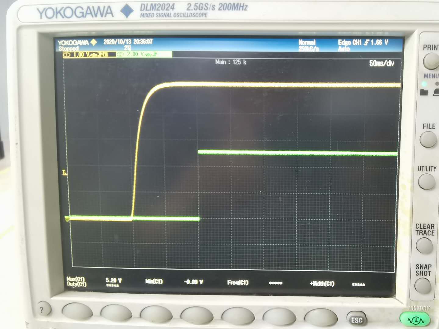
CH1 (yellow) is the power-on waveform of the CLR pin, and CH2 (green) is the trigger output waveform.
When the oscilloscope scan is placed on the CLK pin, the conversion output remains predetermined.
Please help analyze whether it is improper use or the material itself may be defective.
thank you!