Part Number: SN74AUP1T14
Other Parts Discussed in Thread: SN74LVC1G14
Hey Team,
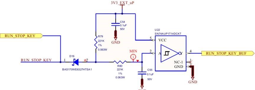
We’re seeing something peculiar with a SN74AUP1T14 Schmitt-trigger inverter as used in the following circuit:
The RUN_STOP_KEY signal on the left goes to a membrane switch in our keypad. The signal is pulled to ground when the key is pressed. The RUN_STOP_KEY_BUF signal on the right goes directly into an i.MX 6UL microprocessor. One of our software engineers noticed that a single keypress was generating two rising edge interrupts. The first interrupt occurred as expected when the key was pressed, but a second occurred after the key was released and the output of the inverter went low. This behavior was also observed when a function generator replaced the mechanical switch; however the problem went away when an SN74LVC1G14 replaced the AUP1T logic device.
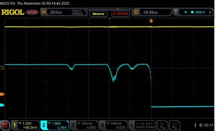
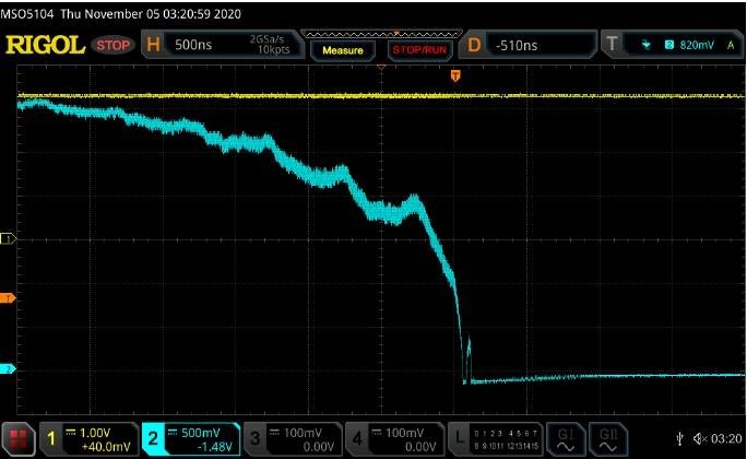
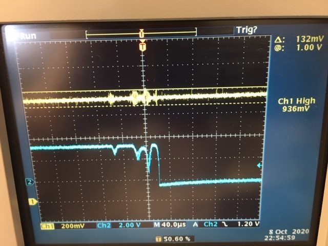
The following oscilloscope images show the output of the inverter by the blue trace and the 3V3_EXT_uP supply voltage by the yellow trace. I was curious to know if the supply was ‘moving’ when the switching occurred. As can be seen the output has an unusual characteristic that I can’t explain.
After changing the horizonal and vertical resolution the signal looks like it could falsely trigger a rising edge interrupt due to the speed at which the microprocessor responds. The i.MX 6UL requires an input transition time of less than 25ns so with a slow transition and noise I believe this is causing the problem.
Do you see any concerns with the way we’re using the part? I thought maybe the time constant on the input was just too long, but speeding it up by removing capacitor C55 didn’t seem to help.


