Part Number: TM4C123GH6PGE
Other Parts Discussed in Thread: EK-TM4C123GXL, EK-TM4C1294XL, TM4C123GH6PM
Hello Everyone
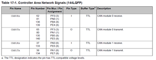
I cannot communicate through the Can0 port on my custom board that I set up with tm4c123gh6pge, but I can communicate comfortably from the CAN1 port with the exact same code.
Likewise, on texas development boards (tm4c1294encpdt), I cannot communicate via CAN0 port, but I can communicate with the same code using CAN1.
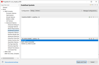
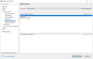
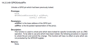
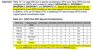
What I'm wondering is, do I need to apply a separate configuration to use CAN0 base on texas MCU's?
Thanks, regards.