This thread has been locked.

If you have a related question, please click the "Ask a related question" button in the top right corner. The newly created question will be automatically linked to this question.

AM2634: MCSPI Receive Only Mode (12..16Bit) with DMA and endless operation?

Part Number: AM2634
Other Parts Discussed in Thread: SYSCONFIG

Hi,

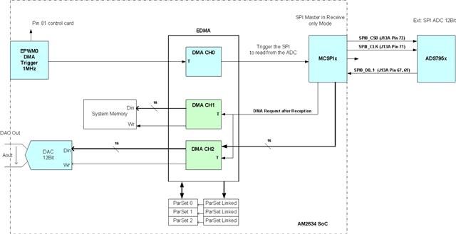
using the following setup I try to figure out how to configure the AM2634 SoC to receive serial data over SPI from an external ADC,
and to store those data in the system memory and for control purpose only I write it to the on Chip DAC port for verification.

- TI CCS Version: 11.2.0.00007
- SysConfig 1.14.0
- MCU SDK for AM263x Version: 8.5.0.24

The drawing below shall illustrate what I try to achieve:

Q: What is the best example I should look into in order to adapt it for the scenario shown above?

I tried to modify "mcspi_loopback_dma_am263x-cc_r5fss0-0_nortos_ti-arm-clang" within the SDK example section. However I am having troubles lowering
the SPI clock to 10MHz (in SysCfg). Doing so the example stops working. I am not sure if the current tool setup is actual enough to achieve what I want to
accomplish. I can measure the SPI_CLK it is being lowered to 10MHz. However it seems that the driver is somehow 'stuck' and never returns ...

Any hint would be appreciated
Markus

  • Hi Markus,

    I did reproduce the issue you reported.  I tried the same example with the MCU+SDK for AM263x 08.05.00.24. Bit rate works for 50Mhz, 25Mhz, but it fails at 12.5Mhz and 10Mhz, 6.25Mhz and 5Mhz. I also checked the values of MCSPI0_CH0CONF for different bit rates. They are all looked OK. I will file a JIRA ticket against this issue soon. It may take a few days to root cause and find a fix for it. Thank you so much for your patience.

    Best regards,

    Ming

  • Hi Ming,

    thank you for picking up. I do have some additional information. We intend to use one of the 12Bit 1MSample ADC from TI. However I am not sure if this will work. Looking at the data sheet of those converters I do get the impression that the falling edge of the CSn signal is needed to move the acquisition to the sampling step within the ADC conversion. See ds extract from TI's product.

    I was able to change the demo program, still it crashes for a reason I don't know, to generate a 20MHz clock for 16clocks. What bothers me is the time between the falling edge of the Csn signal and the first rising clock edge. Maybe this is driver related. However in my measurements I do measure independent of the selected speed ~600ns until the first rising clock edge.

    Q: How can I shorten this time? Is this driver related or hardware related?

    Also the CSn rising edge must be much closer to the end of the SPI transfer.

    Q: Is this a SW driver issue?

    Update!

    I was able to reduce the timing after the falling edge of the chip select (blue scope trace) within the sysconfig tool. The reduction is to a half SPI clock cycle. This is done by changing the 'Mode of Operation' to Multi Master Mode. This seems to be needed even if there is no multi master scenario. Anyway the clock is being generated but the application is still crashing. A side note to sysconfig: If you do this change the tool will flag a configuration error with respect to the DMA_TRIGGER. You can easily repair this by re-assigning the correct order within the MCSPI configuration section and the error will disappear. Seems to be something that happens in the latest version 1.15.0 as well.

    br
    Markus

  • Hi Markus,

    I am glad to see you find a way to solve the CS low too long issue.

    The multiple master case in syscfg is simply means the MCSPI instance needs to use the chip select to control more than one slaves. It does not mean there are multiple masters. 

    Regarding to the MCSPI lock up issue when the bit rate is set to below 25Mhz, a JIRA ticket has been filed and the SW team will look into it.

    Can I close this thread for now? You can reopen it anytime.

    Best regards,

    Ming

  • Hi Ming,

    Update:

    I think I discovered the 'problem' with the lower SPI clock frequencies. If you reduce the loop counter to one it will work

    for(j = 0U; j < APP_MCSPI_TRANSFER_LOOPCOUNT; j++) {

           transferOK = MCSPI_transfer(gMcspiHandle[CONFIG_MCSPI0], &spiTransaction);

           if (spiTransaction.status != MCSPI_TRANSFER_COMPLETED) {
               DebugP_log("--> MCSPI Transfer un-successful ...\r\n");
           }
        }

    "APP_MCSPI_TRANSFER_LOOPCOUNT" in the original demo program was 10 and not 1. Therefore the loop gets over and over.
    It should however kind of wait until the transaction from the previous call completes. However it doesn't. In may opinion it is kind of
    a sub-optimal concept to integrated the DMA channel configuration into this transaction function. I may write now my own transfer
    function in order to be able to setup the EDMA in a way that better suits my requirements shown in the picture at the beginning of this
    thread. I close this thread with confidence now.

    br
    Markus

    - I can close this case. However how can I get the status of the JIRA case being opened?
    - The following questions still needs to be resolved:

    Q1: I want a periodic trigger from one of the EPWM's to start the SPI readings. How do I achieve this? See 1st img within this thread.
    Q2: EDMA configuration is a point. In the past I did it in a separate code blocks. For the MCSPI it is somehow part of the associated library. I will need to figure out how this is being accomplished without creating to much of confusion.

    Anyway I look forward to get notified somehow on the JIRA case while it evolves.

    br
    Markus

  • Hi Markus,

    I would suggest you to create a new thread for the Q1, since it is a separate topic, so that we can assign the domain expert for the EPWM --> MCSPI --> ADC using EDMA.

    As of the Q2, we have filed a JIRA ticket MCUSDK-9595 for it. The software team will investigate it further.

    Best regards,

    Ming