This thread has been locked.

If you have a related question, please click the "Ask a related question" button in the top right corner. The newly created question will be automatically linked to this question.

TMS570LC4357: Filtered glitch issue in PWM Digital Compare Module (DC)

Part Number: TMS570LC4357

Hi team,

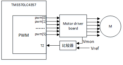
When driving a brushless three-phase motor with PWM, the motor drive board voltage is monitored using an analogue compare chip and connected to the TZ input of the PWM: 

The signal is captured by an oscilloscope, and there are glitches on the signal that the analogue comparator outputs to the PWM TZ, and the glitch occurs in an unfixed position for each PWM cycle. The customer wants to filter the glitch on the TZ through the filtering function in the DC of the digital compare module in the PWM. 

Assuming that T1 and T2 are two adjacent PWM periods (T2 is after the T1 time) in the figure below, as per the TMS570LC4357 PWM module DC section:

  • The window counter begins counting after the offset counter counts down to 0
  • Glitches in the window range are filtered
  • The DCCAP register captures the time-base counter value when a DCEVFILT event occurs. 

Based on the above premise, assuming that the glitch occurs in the middle of the TZ signal at T1 time, first the software needs to set the DC capture on and then read the value of the DCCAP register to set the offset length in the figure below with the value of the time base counter captured in DCCAP. The window range is also set according to the width of the glitch, so that the window filter range covers the area where the glitch occurs, for the purpose of filtering the glitch. However, if the location of the glitch on the TZ signal changes on the next cycle (T2 time), for example, the glitch occurs in the area after TZ, because the T1 time configured offsetn and window cannot meet the T2 time, resulting in the configured filter interval at T1 time to fail to filter the glitch at T2 time. 

1) Does the DC filter glitch function in the PWM module only support filtering the glitches that are fixed on the TZ signal? 

2) If the width of each glitch is different, how should software dynamically adjust the window counter value to cover the area where the glitch occurs? 

Could you help check this case? Thanks.

Best Regards,

Cherry

  • Hi Cherry,

    1) Does the DC filter glitch function in the PWM module only support filtering the glitches that are fixed on the TZ signal? 

    Yes, you are right. The DC filter cannot change its window dynamically based on the noise glitches, it always has a fixed width based on the DCFWINDOW register value and which will start right after the DCFOFFSET which will again start immediately after the CTR = PRD or CTR = 0.

    2) If the width of each glitch is different, how should software dynamically adjust the window counter value to cover the area where the glitch occurs? 

    This window cannot be adjusted dynamically.

    But i can suggest you one way to eliminate this glitches. There is one option to control the ePWM inputs as shown below

    Actually, the ePWM nTZ inputs can be configured in any of the three methods listed above using IOMM module

    1. Asynchronous Input

    2. Double-VCLK3-Synchronized Input

    3. Double-VCLK3-Synchronized and 6-VCLK3-Filtered Input

    1. Asynchronous Input:

    In this method the change in the input signal(nTZ) is directly passed to the  ePWM module without any filtering.

    2. Double-VCLK3-Synchronized Input:

    In this method any change in the input signal for at least 2VCLK3 cycles will only pass to the ePWM module.

    For example:

    Let's say nTZ1 is in logic high for long time and now it is changed to the logic low, so this low pulse will not immediately pass to the ePWM module instead of the IOMM module will verify whether the low pulse durations is at least 2VCLK3 cycles or not. If the low pulse duration is less than the 2VCLK3 cycles, then IOMM module will not pass that low pulse to the ePWM module, so the ePWM module will read the nTZ1 as logic high only.

    So, in this method, any noise of the width less than 2VCLK3 cycles will get eliminated by IOMM module.

    3. Double-VCLK3-Synchronized and 6-VCLK3-Filtered Input:

    In this method any change in the input signal for at least 6 VCLK3 (+2 VCLK3) cycles will only pass to the ePWM module. That means the pulse width with size of 8VCLK3 cycles only will get passed to the ePWM module by IOMM module.

    For example:

    Let's say nTZ1 is in logic high for long time and now it is changed to the logic low, so this low pulse will not immediately pass to the ePWM module instead of the IOMM module will verify whether the low pulse durations is at least 8VCLK3 cycles or not. If the low pulse duration is less than the 8VCLK3 cycles, then IOMM module will not pass that low pulse to the ePWM module, so the ePWM module will read the nTZ1 as logic high only.

    So, in this method, any noise of the width less than 8VCLK3 cycles will get eliminated by IOMM module.

    So, use any of the method 2 or 3 based on the noise glitches size you are seeing on the nTZ input.

    --

    Thanks & regards,
    Jagadish.