


Part Number: MCU-PLUS-SDK-AM243X
Other Parts Discussed in Thread: SYSCONFIG
Hello experts,
I'm developing support for custom flash device "MX25L12833FM2I-10G".
I'm having troubles using the flash in 1S-1S-4S.
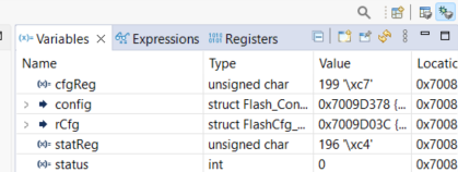
I managed to configure correctly the flash in the 1S-1S-4S protocol. After configuration the bit6 (QE, quad enable) of the status word is set correctly and the amount of dummy cycles is set to 10 (bit6/7 of configuration register), as shown in the image, where cfgReg = configuration register and statReg = status register.
The problem occurs when I execute a QREAD command (0x6B):
I'm using the ospi_flash_io example provided by the SDK, where it writes an array of values to the flash (from 0 to 255 in crescent order) and then reads back this values.
In the read buffer I'm getting this values instead:
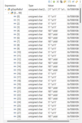
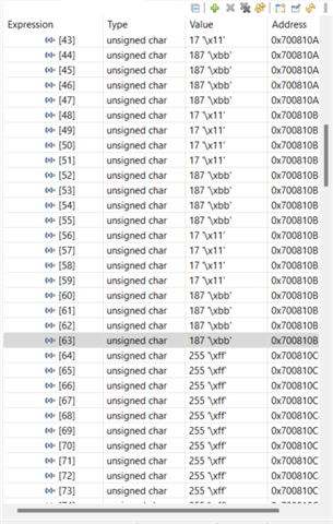
This response from the flash makes me wonder if all the 4 spi pins (D0,D1,D2,D3) are actually being used or if I'm missing something the the peripheral configuration.
Here you can find the sysconfig file from my project
/**
 * These arguments were used when this file was generated. They will be automatically applied on subsequent loads
 * via the GUI or CLI. Run CLI with '--help' for additional information on how to override these arguments.
 * @cliArgs --device "AM243x_ALX_beta" --package "ALX" --part "ALX" --context "r5fss0-0" --product "MCU_PLUS_SDK_AM243x@09.00.00"
 * @versions {"tool":"1.18.0+3266"}
 */

/**
 * Import the modules used in this configuration.
 */
const flash      = scripting.addModule("/board/flash/flash", {}, false);
const flash1     = flash.addInstance();
const clock      = scripting.addModule("/kernel/dpl/clock");
const debug_log  = scripting.addModule("/kernel/dpl/debug_log");
const mpu_armv7  = scripting.addModule("/kernel/dpl/mpu_armv7", {}, false);
const mpu_armv71 = mpu_armv7.addInstance();
const mpu_armv72 = mpu_armv7.addInstance();
const mpu_armv73 = mpu_armv7.addInstance();
const mpu_armv74 = mpu_armv7.addInstance();

/**
 * Write custom configuration values to the imported modules.
 */
flash1.$name                         = "CONFIG_FLASH0";
flash1.device                        = "CUSTOM_FLASH";
flash1.flashSize                     = 16777216;
flash1.flashBlockSize                = 65536;
flash1.dummy_isAddrReg               = false;
flash1.dummy_cfgReg                  = "0x00000000";
flash1.addressByteSupport            = "0";
flash1.idNumBytes                    = 5;
flash1.modeClksRd                    = 0;
flash1.fourByteEnableSeq             = "0x80";
flash1.flash444Seq                   = "0x00";
flash1.flashManfId                   = "0xC2";
flash1.flashDeviceId                 = "0x2018";
flash1.cmdBlockErase4B               = "0xFF";
flash1.cmdSectorErase4B              = "0xFF";
flash1.flashQeType                   = "2";
flash1.protocol                      = "1s_1s_4s";
flash1.dummy_cmdRegRd                = "0x15";
flash1.dummy_cmdRegWr                = "0x01";
flash1.dummy_mask                    = "0xC0";
flash1.dummyClksRd                   = 10;
flash1.dummy_shift                   = 6;
flash1.dummy_bitP                    = 3;
flash1.fname                         = "MX25L128";
flash1.enable4BAddr                  = false;
flash1.cmdRd                         = "0x6B";
flash1.quirks                        = "NULL";
flash1.peripheralDriver.$name        = "CONFIG_OSPI0";
flash1.peripheralDriver.inputClkFreq = 100000000;

debug_log.enableUartLog        = true;
debug_log.uartLog.$name        = "CONFIG_UART_LOG";
debug_log.uartLog.UART.$assign = "USART0";

mpu_armv71.$name             = "CONFIG_MPU_REGION0";
mpu_armv71.size              = 31;
mpu_armv71.attributes        = "Device";
mpu_armv71.accessPermissions = "Supervisor RD+WR, User RD";
mpu_armv71.allowExecute      = false;

mpu_armv72.$name             = "CONFIG_MPU_REGION1";
mpu_armv72.size              = 15;
mpu_armv72.accessPermissions = "Supervisor RD+WR, User RD";

mpu_armv73.$name             = "CONFIG_MPU_REGION2";
mpu_armv73.baseAddr          = 0x41010000;
mpu_armv73.size              = 15;
mpu_armv73.accessPermissions = "Supervisor RD+WR, User RD";

mpu_armv74.$name             = "CONFIG_MPU_REGION3";
mpu_armv74.baseAddr          = 0x70000000;
mpu_armv74.size              = 21;
mpu_armv74.accessPermissions = "Supervisor RD+WR, User RD";

/**
 * Pinmux solution for unlocked pins/peripherals. This ensures that minor changes to the automatic solver in a future
 * version of the tool will not impact the pinmux you originally saw.  These lines can be completely deleted in order to
 * re-solve from scratch.
 */
flash1.peripheralDriver.OSPI.$suggestSolution      = "OSPI0";
flash1.peripheralDriver.OSPI.CLK.$suggestSolution  = "OSPI0_CLK";
flash1.peripheralDriver.OSPI.CSn0.$suggestSolution = "OSPI0_CSn0";
flash1.peripheralDriver.OSPI.D3.$suggestSolution   = "OSPI0_D3";
flash1.peripheralDriver.OSPI.D2.$suggestSolution   = "OSPI0_D2";
flash1.peripheralDriver.OSPI.D1.$suggestSolution   = "OSPI0_D1";
flash1.peripheralDriver.OSPI.D0.$suggestSolution   = "OSPI0_D0";
debug_log.uartLog.UART.RXD.$suggestSolution        = "UART0_RXD";
debug_log.uartLog.UART.TXD.$suggestSolution        = "UART0_TXD";
Thank you in advance,
Best Regards,
Andrea F,


