This thread has been locked.

If you have a related question, please click the "Ask a related question" button in the top right corner. The newly created question will be automatically linked to this question.

MCU-PLUS-SDK-AM263X: Continuous sampling of multiple ADCs to DMA buffers

Part Number: MCU-PLUS-SDK-AM263X
Other Parts Discussed in Thread: SYSCONFIG

I want to configure multiple ADC channels to continuously read voltage and store the samples to RAM

The frequency of the sampling needs to be about 200Hz for all channels. For this reason, I want to use DMA.

I am trying to do proof-of-concept on the TI-TMDSCNCD263-AM263x Sitara Control Card.

It seems that the SDK example: adc_soc_continuous_dma_am263x-cc_r5fss0-0_nortos_ti-arm-clang.

I have this example working, but the SDK example fills the DMA buffers, and then stops. This is not what I want.

I want to modify example such that an application-layer event, at any time, can copy the DMA buffer to get a snapshot of the recent samples. Disabling interrupts momentarily, if needed, to copy the data is not a problem.

I experimented removing the function calls in the ISRs (seen here) which I suspected may be stopping the 'continuous ADC to DMA' that I want. 

void App_adcISR(void *args)
{
    /* Remove ePWM trigger */
    EPWM_disableADCTrigger(CONFIG_EPWM0_BASE_ADDR, EPWM_SOC_A);

    /* Disable this interrupt from happening again */
    ADC_disableInterrupt(gAdc1baseAddr, ADC_INT_NUMBER1);
}

void App_dmach0ISR(Edma_IntrHandle intrHandle, void *args)
{
    SemaphoreP_Object *semObjPtr = (SemaphoreP_Object *)args;
    DebugP_assert(semObjPtr != NULL);

    /* Stop the ADCs by removing the trigger for SOC0 */
    ADC_setInterruptSOCTrigger(gAdc1baseAddr, ADC_SOC_NUMBER0,
                               ADC_INT_SOC_TRIGGER_NONE);
    ADC_setInterruptSOCTrigger(gAdc2baseAddr, ADC_SOC_NUMBER0,
                               ADC_INT_SOC_TRIGGER_NONE);

    /* Post the semaphore to signal end of DMA transfer */
    SemaphoreP_post(semObjPtr);
}

However, when I set a breakpoint in App_dmach0ISR() it only gets hit once.

Please advise on what needs to be done to achieve 'continuous ADC to DMA'.

  • Hi Tollman,

    The example showcases how we could use an ADC INT to trigger the DMA transfers, in this case, the ADC results to a buffer in the RAM. The DMA is configured for a certain number of transfers, not more than that. if you want an infinite transfers, you will have to modify the DMA configurations to have a very large number of transfers before the param set expires, and when param sets expire, take an Interrupt to re-configure for another large number of transfers. 

    Your request is, on-demand from Application, the DMA should transfer the latest conversion data to the RAM, which is not a Continuous ADC-DMA transfer. Please correct me if I understood it wrong. But, if so, you don't have to configure the DMA to be triggered by the ADC, instead, can be triggered by SW, like any other polled-transfer of DMA, refer to :  https://software-dl.ti.com/mcu-plus-sdk/esd/AM263X/09_01_00_41/exports/docs/api_guide_am263x/EXAMPLES_DRIVERS_EDMA_POLLED_TRANSFER.html

    please clarify which approach suits you, so that we can try to help you. Smile

    thanks and regards,

    Madhava

  • Thanks for the response Madhava. 

    After reviewing what you posted, reviewing the SDK example you referenced, and reading the reference manual again, it seems like a viable solution may be to use the field:

      Link Address (LINK)

    ... in the EDMA Channel PaRAM Set. 

    I think this should enable the continuous transfer of ADC results to alternating (ping-pong) RAM buffers without processor intervention.

    Is this correct?

    Regards,

    Tollman

  • Tollman,

    Yes. That approach would be correct. The edma linked transfer example can be used for referring such configuration.

    Thanks and regards,

    Madhava

  • Madhava,

     Sorry for the delay, this project was preempted by other tasks.


    I tried to modify the SDK Example:

      adc_soc_continuous_dma_am263x-cc_r5fss0-0_nortos_ti-arm-clang

    to use two PaRAM Sets that alternate.

     I tried to achieve this by:

    • Creating a 2nd PaRAM Set.
    • Modifying linkAddr in the 1st  PaRAM Set to ‘point to’ the 2nd and vice versa. I’m using value set by  EDMA_allocParam() by for these values, but I’m not certain this is correct.
    • Modifying bCntReload to the ‘table size’. I’m not certain this is correct. I tried using both the table size, and zero for this value.
    • Exclude the statements in the ISRs that were disabling the ADC sampling after the buffer is full. See (#ifdef STOP_SAMPLING_WHEN_BUFFER_FULL).
    • Make the main loop a ‘forever loop’ so I can set a breakpoint and check the gAdc1DataBuffer, and gAdc2DataBuffer.


    Results:

    • App_dmach0ISR() does not execute multiple times as desired. I want the ISR to execute after each PaRAM Set switch.
    • When halting seconds apart in the ‘forever loop’, the gAdc1DataBuffer, and gAdc2DataBuffer values do not change as desired.


    I am attaching the modified adc_soc_continuous_dma_am263x-cc_r5fss0-0_nortos_ti-arm-clang project.

    What is wrong?

    Regards,

    Scott

    adc_soc_continuous_dma_am263x-cc_r5fss0-0_nortos_ti-arm-clang(20240220_0745-PingPongTest01).zip

  • Hi Scott,

    Modifying linkAddr in the 1st  PaRAM Set to ‘point to’ the 2nd and vice versa. I’m using value set by  EDMA_allocParam() by for these values, but I’m not certain this is correct.

    Could you try the linking using the API as follows? this is essentially making param 1 point to param 2. once 1 is exhausted, 2 will be copied over. also, param 2 points to 2, so that when copied over to param 1, it is still liked to the param 2 to get copied over after exhaustion.

    • EDMA_linkChannel(baseAddr, param1, param2);
    • EDMA_linkChannel(baseAddr, param2, param2);
    Modifying bCntReload to the ‘table size’. I’m not certain this is correct. I tried using both the table size, and zero for this value

    I am not sure if this is required for the given usecase. 

    void App_adcISR(void *args)
    {
    #ifdef   STOP_SAMPLING_WHEN_BUFFER_FULL
        /* Remove ePWM trigger */
        EPWM_disableADCTrigger(CONFIG_EPWM0_BASE_ADDR, EPWM_SOC_A);
    
        /* Disable this interrupt from happening again */
        ADC_disableInterrupt(gAdc1baseAddr, ADC_INT_NUMBER1);
    #endif  // STOP_SAMPLING_WHEN_BUFFER_FULL
    }
    

    this is used to stop ADCs getting triggered from EPWM after the first, because the ADC SOCs are configured to get a trigger from ADCINT as well as EPWM_SOCx. now there is only a ADCINT to continuously trigger the ADC SOCs. so you can remove the #ifdef here.

    the example is designed for an errata workaround. so there is an empty_param paramset, that copies 1 soc, then chains to the param1. now, param1 will transfer 1 soc. once param1 is exhausted, we want our param2 to get transfered, but note that, the empty_param is not linked to any and will be left at exhaustion, and will void any further triggers and will not chain to param1 anymore. 

    so the steps would be...

    1. both empty_param, param1 to have duplicates. actual paramsets linked to duplicates, duplicates linked to themselves.  
    2. Chaining should enabled for originals, as well as duplicates, so that when copied over the chaining configurations remain.
    3. if you wish to increase the number of SOCs to be transfered in the actual paramset, we might have to change it to AB sync mode on the actual paramsets and increase the bCnt. but this can be tried later once the basic case is working. 

    thanks and regards,

    Madhava

  • Hi Madhava,

    Thanks for the help.

    I made the changes that you suggested. Now I see the ADC buffers continuously update, and App_dmach0ISR() is continuously called. This is good progress.

    I need to sample all 30 Analog inputs round robin at about 1kHz, and process the buffers after 256 samples of each channel. I plan on changing the ADC Clock Prescaler, and SOC configuration in SYSCONFIG accordingly,

    Before doing so, I want to address the buffer organization.

    First, I want to make the ADC results buffers in a multi-dimensional array instead of the individual buffers in the SDK example.

    To do this I define the dimensions:

    /**
      *  Ping-pong buffers
      */
    #define ADC_BUFFER_NUM          (2U)
    
    /**
      *  AM263x ADC modules
      */
    #define ADC_MODULE_NUM          (5U)
    
    /**
      *  AM263x ADC channels per modules
      */
    #define ADC_CHANNEL_NUM          (6U)
    
    /**
      *  Depth of sample buffer per channel.
      */
    #define ADC_SAMPLE_NUM          (256U)
    
    /**
      *  Size of the entire buffer of a Module. (ping or pong)
      *  Note:  x 2 for uint16_t
      */
    #define ADC_MODULE_BUFFER_SIZE  (ADC_CHANNEL_NUM * ADC_SAMPLE_NUM * 2)

    Then define the reault buffer array to hold the results: 

    /**
      *  This buffer holds all analog input data. It is written by EDMA.
      *  All channels for all modules are sampled round robin, with one SOC per channel
      *  For ADC0 AdcInBuf[0][0] will fill completely, then AdcInBuf[0][1] before starting
      *  to fill AdcInBuf[0][0] again switching in a ping-pong pattern. An interrupt is triggered
      *  upon each switch to allow processing.
      */
    uint16_t AdcInBuf[ADC_MODULE_NUM][ADC_BUFFER_NUM][ADC_CHANNEL_NUM][ADC_SAMPLE_NUM];

    Then the App_dmaConfigure() calls are adjusted to be called for each ADC module. I'm not confident in all the parameters here:

    /* 
     * Configure DMA channels to transfer ADC results.
     * Note: This function assumes the dest buffer points to a 2D (ping pong) buffer of size (ADC_MODULE_BUFFER_SIZE * 2)
     */
    App_dmaConfigure(AdcInBuf[0], ADC_MODULE_BUFFER_SIZE, gEdmaHandle[0],
                ADC0_EDMA_CHANNEL, CONFIG_ADC0_RESULT_BASE_ADDR, &tccAlloc0, EDMA_TEST_EVT_QUEUE_NO_0);
    
    App_dmaConfigure(AdcInBuf[1], ADC_MODULE_BUFFER_SIZE, gEdmaHandle[0],
                ADC1_EDMA_CHANNEL, CONFIG_ADC1_RESULT_BASE_ADDR, &tccAlloc1, EDMA_TEST_EVT_QUEUE_NO_1);
    
    App_dmaConfigure(AdcInBuf[2], ADC_MODULE_BUFFER_SIZE, gEdmaHandle[0],
                ADC2_EDMA_CHANNEL, CONFIG_ADC2_RESULT_BASE_ADDR, &tccAlloc2, EDMA_TEST_EVT_QUEUE_NO_2);
    
    App_dmaConfigure(AdcInBuf[3], ADC_MODULE_BUFFER_SIZE, gEdmaHandle[0],
                ADC3_EDMA_CHANNEL, CONFIG_ADC3_RESULT_BASE_ADDR, &tccAlloc3, EDMA_TEST_EVT_QUEUE_NO_3);
    
    App_dmaConfigure(AdcInBuf[4], ADC_MODULE_BUFFER_SIZE, gEdmaHandle[0],
                ADC4_EDMA_CHANNEL, CONFIG_ADC4_RESULT_BASE_ADDR, &tccAlloc4, EDMA_TEST_EVT_QUEUE_NO_4);
    
    App_dmaConfigure(AdcInBuf[5], ADC_MODULE_BUFFER_SIZE, gEdmaHandle[0],
                ADC5_EDMA_CHANNEL, CONFIG_ADC5_RESULT_BASE_ADDR, &tccAlloc5, EDMA_TEST_EVT_QUEUE_NO_5);

    Then the App_dmaConfigure() is modified to account for the ping-pong scheme.

    uint16_t App_dmaConfigure(
            const uint16_t *table, uint16_t table_size,
            EDMA_Handle dma_handle, uint32_t dma_ch,
            uint32_t adc_base, uint32_t *tccAlloc, uint32_t event_queue_number)
    {
    //...

    ... App_dmaConfigure() ping buffer params

    //...
        //Each CSL_ADC_RESULT_ADCRESULTx address offset is 2-bytes apart.
        //Param set 1
        EDMA_configureChannelRegion(baseAddr, regionId, EDMA_CHANNEL_TYPE_DMA,
                dmaCh, tcc, param1, event_queue_number);
        /* Program Param Set 1 (ping buffer)*/
        EDMA_ccPaRAMEntry_init(&edmaParam);
        edmaParam.srcAddr       = (uint32_t) SOC_virtToPhy((void *)(adc_base+CSL_ADC_RESULT_ADCRESULT0));
        edmaParam.destAddr      = (uint32_t) SOC_virtToPhy((void *)table);
        

    ... App_dmaConfigure() pong buffer params

        //Param set 2
        EDMA_configureChannelRegion(baseAddr, regionId, EDMA_CHANNEL_TYPE_DMA,
                dmaCh, tcc, param1, event_queue_number);
        /* Program Param Set 2 (pong buffer)
         * Note: destAddr = table + table_size
         */
       
        EDMA_ccPaRAMEntry_init(&edmaParam);
        edmaParam.srcAddr       = (uint32_t) SOC_virtToPhy((void *)(adc_base+CSL_ADC_RESULT_ADCRESULT0));
        edmaParam.destAddr      = (uint32_t) SOC_virtToPhy((void *)table + table_size); 

    I have not addressed the  'AB sync mode' issue yet, I will address that later.

    The edmaParam.srcAddr  is assuming that each CSL_ADC_RESULT_ADCRESULTx address offset is 2-bytes apart, but I expect that the transfer will copy CSL_ADC_RESULT_ADCRESULTx into AdcInBuf[][][x] once the sync mode is setup.

    Does this architecture make sense?

    If so, I will take a stab at configuring the 'AB sync mode' parameters.

    Regards,

    Tollman

  • UPDATE:

    I have been researching Synchronized EDMA Transfer.

    I found this forum discussion, that seems to be related:

    2D AB-Syncronized EDMA Transfer - Processors forum - Processors - TI E2E support forums

    Namely, it is transferring blocks of audio samples. I am reviewing this material in anticipation of your response.

  • Hi Tollman,

    Then the App_dmaConfigure() calls are adjusted to be called for each ADC module. I'm not confident in all the parameters here:

    there are only two queues in the DMA. the example was showcasing ADC transfer from each pair.

    please clarify if you have to transfer more number of ADC-SOC-Results in one trigger. beacuse there are only a few INT from ADC but there are 16 SOC/ 6 Channels in each. if so, then you can configure your actual channel to transfer more number of SOC Results in one go. 

    ... App_dmaConfigure() pong buffer params

    in your code, you have the following,     `edmaParam.destAddr      = (uint32_t) SOC_virtToPhy((void *)table + table_size); ` why so? 

    the EDMA in AM263x is capable of advanced transfers in A/AB/ transfers with its linked/chained transfers on DMA/QDMA channels, and with triggers which can be sourced from many peripherals/ subsystems on SoC. I would strongly suggest referring the EDMA sections in the TRM, and the SDK examples of the EDMA for a better integration into the application, which can help you save time on different approaches.  

    thanks, 

    Madhava

  • I have read into the TRM, forum post (referenced above), and training video. I will review the EDMA SDK examples too. 

    I'll try modifying the code with this information to see if I can get it working. 

    In the meantime, regarding your questions:

    -------------------------------------

    <SNIP_1>

    "there are only two queues in the DMA. the example was showcasing ADC transfer from each pair.

    please clarify if you have to transfer more number of ADC-SOC-Results in one trigger. beacuse there are only a few INT from ADC but there are 16 SOC/ 6 Channels in each. if so, then you can configure your actual channel to transfer more number of SOC Results in one go. "

    </SNIP_1>

    I think you mean that since I am doing a round-robin SOC for all channels I can only trigger an event when channel 5 (which is last) conversion completes. The transfer triggered by this event could transfer all six CONFIG_ADCx_RESULT_BASE_ADDR.

    Assuming so, I see in the TRM SPRUJ17E - 7.4.2.7 EOC and Interrupt Operation:

    I do not see how to do this through SysConfig.

    How can I enable one transfer for all results in an ADC module?

     --------------------------------------

    <SNIP_2>

    in your code, you have the following,     `edmaParam.destAddr      = (uint32_t) SOC_virtToPhy((void *)table + table_size); ` why so? 

    </SNIP_2>

    This is meant to point to the ‘pong buffer’ through Params Set 2:

    &AdcInBuf[X][1]

    ... given:

    uint16_t AdcInBuf[ADC_MODULE_NUM][ADC_BUFFER_NUM][ADC_CHANNEL_NUM][ADC_SAMPLE_NUM];

    Does that make sense?

    ---------------------------

    Originally, for Synchronized EDMA TransferI was planning:

    ACNT = 2 (2-bytes, uint16_t). One element.   [ **ParamSet.aCnt** ]
    BCNT = 6 (array of channels, CONTROLSS_ADCx_RESULTy). One frame.  [ **ParamSet.bCnt** ]
    CCNT = 256 (sample depth of one Block)    [ **ParamSet.cCnt** ]

    However, now I am investigating if:

    ACNT = (2 * 6) (2-bytes, uint16_t), * 6 elements/channels. One Frame.   [ **ParamSet.aCnt** ]
    BCNT = 256 (sample depth of one Block)  [ **ParamSet.bCnt** ]
    CCNT =   1 [ **ParamSet.cCnt** ]

    Regards,

    Tollman

  • Hi Tollman,

    I think you mean that since I am doing a round-robin SOC for all channels I can only trigger an event when channel 5 (which is last) conversion completes. The transfer triggered by this event could transfer all six CONFIG_ADCx_RESULT_BASE_ADDR.

    Assuming so, I see in the TRM SPRUJ17E - 7.4.2.7 EOC and Interrupt Operation:

    I do not see how to do this through SysConfig.

    How can I enable one transfer for all results in an ADC module?

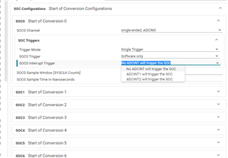
    Yes. say, SOCx till SOCy needs to be in continuous conv mode, set INT 1 to be triggered by SOCy, and SOC x to y are triggered by INT1. also use the same INT 1 to trigger the DMA channel, where instead of aCnt = 2, it can be aCnt = (y-x+1)*2 if A transfer mode. 

    For each SOC in its triggers group, there is a configuration that interrupt can trigger it, [below image for reference] 

    Does that make sense?

    I am sorry, I still don't get it. 

    However, now I am investigating if:

    ACNT = (2 * 6) (2-bytes, uint16_t), * 6 elements/channels. One Frame.   [ **ParamSet.aCnt** ]
    BCNT = 256 (sample depth of one Block)  [ **ParamSet.bCnt** ]
    CCNT =   1 [ **ParamSet.cCnt** ]

    in AB sync transfer, this means a 6 continuous SOCs but then BCNT to be 256 is scary! why would you want to transfer that much in a single trigger if the ADC results are valid for SOC0-15, PPB RES 0-4, a total of 20 registers of 32 bit, and the lower 16 are the valid ones in each. please check here.

    thanks and regards,

    Madhava

  • Hi Madhava,

    I think there may be confusion about what I'm trying to do. Perhaps the confusion is in terminology.

    I decided to start with a simpler SDK example and build towards the final solution.

    This time I started with SDK example:

      adc_soc_epwm_am263x-cc_r5fss0-0_nortos_ti-arm-clang

    Sampling time-base:

    I found that my first mistake is using the term 'continuous'. I think, since I want to sample at about a 1ms period, I can use the PWM to trigger the SOC for each ADC channel. By setting the priority mode to "All priorities based on SOC", I can sample each channel in succession at 1ms in a deterministic order.

    For now, I am only using ADC1, with three channels.

    ADC Int:

    I now make the last SOC (channel 2) the source of ADC1 Interrupt 1.

    DMA Transfer:

    Next, I set the DMA Channel Trigger to ADC1_INT1 (xbar)

    I also resized the Result buffer RAM (the DMA destination) to be (2 bytes * 256 samples, * 3 channels).

    Testing:

    By toggling test points inside the ADC ISR, and DMA ISR, and then inspecting the result buffer, I can see that the sampling is working.

    I connect two inputs to fixed voltages, and the third to a square wave, and the result buffers look good, i.e. the channels are alternating, and ADC1_0 is toggling at the expected rate.

    This is a markup of the buffer to demonstrate:

    After 256 transfers, the DMA ISR triggers.

    Now I only need to add the ping-pong scheme.

    Adding ping-pong:

    Now I need to add the ping pong scheme that, after 256 transfers, swaps buffers. I do not have this working yet, and I suspect one problem may be my use of A, B, C counts.

    You wrote:

    <SNIP>

    in AB sync transfer, this means a 6 continuous SOCs but then BCNT to be 256 is scary! why would you want to transfer that much in a single trigger if the ADC results are valid for SOC0-15, PPB RES 0-4, a total of 20 registers of 32 bit, and the lower 16 are the valid ones in each. please check here.

    </SNIP>

    This makes me think that 'A count' * 'B count' should be 6 for my three channel example. i.e 6 bytes per transfer.

    This implies that C count should be 256.  i.e. I want to sample a 256ms window before the ping-pong swap.

    Please let me know if this makes sense.

    I will experiment in the meantime.

    Also, is the resource:

    KeyStone Architecture Enhanced Direct Memory Access (EDMA3) Controller (Rev. B) (ti.com)

    ... valid for AM263x?

    Regards,

    Tollman

  • Hi Tollman,

    yes the doc you shared for EDMA is valid for AM263x, but the set of triggers / SOC integration might differ.

    thanks,

    Madhava

  • Hi Madhava,

    I did some experimenting with C count == 256.

    However, based on my test points, and the values in the results buffer it seems that:

    1. Ping buffer fills after 256 frames and DMA interrupt occurs.
    2. Next Pong buffer fills after 256 frames and DMA interrupt occurs.
    3. The last frame of the pong buffer updates upon each ADC interrupt and each ADC interrupt triggers a DMA interrupt.

    i.e. The DMA is 'stuck' at the end of the pong buffer, and ping buffer never updates after the initial 256 frames.

    My Param Set configuration is in the code below: 


        //ConfigureChannelRegion for Param set 1
        EDMA_configureChannelRegion(baseAddr, regionId, EDMA_CHANNEL_TYPE_DMA,
                dmaCh, tcc, param1, event_queue_number);
    
        /* Program Param Set 1 */
        EDMA_ccPaRAMEntry_init(&edmaParam);
        edmaParam.srcAddr       = (uint32_t) SOC_virtToPhy((void *)(adc_base+CSL_ADC_RESULT_ADCRESULT0));
        edmaParam.destAddr      = (uint32_t) SOC_virtToPhy((void *)buf1);
        edmaParam.aCnt          = (uint16_t) 2 * 3;
        edmaParam.bCnt          = (uint16_t) 1;
        edmaParam.cCnt          = (uint16_t) buf_size;
        edmaParam.bCntReload    = 1;
        //edmaParam.bCntReload    = buf_size;
        edmaParam.srcBIdx       = (int16_t) EDMA_PARAM_BIDX(0);
        edmaParam.destBIdx      = (int16_t) EDMA_PARAM_BIDX(0);
        edmaParam.srcCIdx       = (int16_t) 0;
        edmaParam.destCIdx      = (int16_t) 2 * 3;
        edmaParam.linkAddr      = 0xFFFFU;
        edmaParam.srcBIdxExt    = (int8_t) EDMA_PARAM_BIDX_EXT(0);
        edmaParam.destBIdxExt   = (int8_t) EDMA_PARAM_BIDX_EXT(0);
        edmaParam.opt           = (EDMA_OPT_TCINTEN_MASK |
                                  ((((uint32_t)tcc) << EDMA_OPT_TCC_SHIFT) & EDMA_OPT_TCC_MASK));
        /* Enabling the Interrupt for Transfer complete of all the data */
        EDMA_setPaRAM(baseAddr, param1, &edmaParam);
    
    
        //ConfigureChannelRegion for Param set 2
        //EDMA_configureChannelRegion(baseAddr, regionId, EDMA_CHANNEL_TYPE_DMA,
        //            dmaCh, tcc, param2, event_queue_number);
    
        EDMA_ccPaRAMEntry_init(&edmaParam);
        edmaParam.srcAddr       = (uint32_t) SOC_virtToPhy((void *)(adc_base+CSL_ADC_RESULT_ADCRESULT0));
        edmaParam.destAddr      = (uint32_t) SOC_virtToPhy((void *)buf2);
        edmaParam.aCnt          = (uint16_t) 2 * 3;
        edmaParam.bCnt          = (uint16_t) 3;
        edmaParam.cCnt          = (uint16_t) buf_size;
        edmaParam.bCntReload    = 1;
        //edmaParam.bCntReload    = buf_size;
        edmaParam.srcBIdx       = (int16_t) EDMA_PARAM_BIDX(0);
        edmaParam.destBIdx      = (int16_t) EDMA_PARAM_BIDX(0);
        edmaParam.srcCIdx       = (int16_t) 0;
        edmaParam.destCIdx      = (int16_t) 2 * 3;
    
        edmaParam.linkAddr      = 0xFFFFU;
        edmaParam.srcBIdxExt    = (int8_t) EDMA_PARAM_BIDX_EXT(0);
        edmaParam.destBIdxExt   = (int8_t) EDMA_PARAM_BIDX_EXT(0);
        edmaParam.opt           = (EDMA_OPT_TCINTEN_MASK |
                                  ((((uint32_t)tcc) << EDMA_OPT_TCC_SHIFT) & EDMA_OPT_TCC_MASK));
    
        /* Enabling the Interrupt for Transfer complete of all the data */
        EDMA_setPaRAM(baseAddr, param2, &edmaParam);
    
        EDMA_linkChannel(baseAddr, param1, param2);
        EDMA_linkChannel(baseAddr, param2, param1);
    

    Do  you see the problem?

    Regards,

    Tollman

  • Hi TollMan,

    Do  you see the problem?

    yes. you are linking in this manner : param1 -> param2, param2 -> param1. but by the time param2 is exhausted and checking to link with param1, which is now itself exhausted. you have to link param1-> param2, param2->param2. then again, if you need buffers to be different, i suggest, param1 (buf1) -> param2 (buf2) -> param3 (buf1)->param2(buf2).

    thanks and regards, 

    Madhava

  • Madhava

    By using a third Param Set (param3), and Linking param3 to param2, the ping-pong buffer scheme works.

    Thanks for the help!

    Tollman