This thread has been locked.

If you have a related question, please click the "Ask a related question" button in the top right corner. The newly created question will be automatically linked to this question.

MSPM0G3507: Delay and ADC Question

Part Number: MSPM0G3507
Other Parts Discussed in Thread: SYSCONFIG

Tool/software:

I am still porting the touch aspect of the K350 boosterpack and GRLib

In the MSP432P401R code they have this:

static void touch_delay(){
    uint32_t i = 0;
    uint32_t time = 480000;

    for(i = 0; i < time; i++)
    {
        ;
    }
}

which, because of some other comments I believe is a 4ms delay.

Other than adding some "volatiles" to this code, is there a better way to implement a delay? would delay_cycles() be better? Interrupts still happen during a delay_cycle() chain, right?

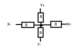
Also, because I have to switch between GPIO and ADC, I do the following:

/* Sample the X+ ADC channel to check if there is currently a touch. */
    SYSCFG_DL_ADC12_0_init();
    gCheckADC0 = false;

    DL_ADC12_startConversion(ADC12_0_INST);

    while (false == gCheckADC0) {
        __WFE();
    }

    aDCTemp = DL_ADC12_getMemResult(ADC12_0_INST, DL_ADC12_MEM_IDX_0);

which I stole from one of the ADC examples.

I notice that I sometimes get 0 values returned when I do this. Do I need to allow more time between the init and the startConversion?

  • Hi,

    Other than adding some "volatiles" to this code, is there a better way to implement a delay? would delay_cycles() be better? Interrupts still happen during a delay_cycle() chain, right?

    Yes. interrupts will still happen during delay_cycle. A better way is to use a timer interrupt to generate an accurate 4ms delay.

    I notice that I sometimes get 0 values returned when I do this. Do I need to allow more time between the init and the startConversion?

    I do not think it related to the time between init and start conversion. How do you switch your GPIO function from GPIO to ADC? It could related to the switch issue. 

    Best regards,

    Cash Hao

  • First, I want to say that it was TI that came up with that delay routine, not me. 8^)

    Feel free to refer to the MSP432P401R GRLib code that this is based on. 8^)

    I came up with my GPIO/ADC switch by using some SysConfig Abuse. I set up the GPIO's in sysconfig and built the project. I stole the DL_CONFIG initialization code. Then I set up the ADC's in sys config, and left it that way when I compiled the project so that the ADC code is in the sysconfig init code, but the GPIO's aren't. So in my code I do this:

    I have 4 pins: XMINUS, XPLUS, YMINUS, YPLUS.

    To get the X value I want to make the X+ and X- pins GPIO outputs, make the Y- pin High Z and read the ADC_1, channel 6 on PB19.

    /* Set X+ and X- as output and Y- as input (floating). */
        DL_GPIO_initDigitalOutput(GPIO_TOUCH_XPLUS_IOMUX);
        DL_GPIO_initDigitalOutput(GPIO_TOUCH_XMINUS_IOMUX);
    
        DL_GPIO_enableOutput(GPIO_TOUCH_XPLUS_PORT, GPIO_TOUCH_XPLUS_PIN);
        DL_GPIO_enableOutput(GPIO_TOUCH_YMINUS_PORT, GPIO_TOUCH_YMINUS_PIN);
    
        // Set to Hi Z?
        DL_GPIO_disableOutput(GPIO_TOUCH_YPLUS_PORT, GPIO_TOUCH_YPLUS_PIN);
        DL_GPIO_disableOutput(GPIO_TOUCH_YMINUS_PORT, GPIO_TOUCH_YMINUS_PIN);
    
        DL_GPIO_clearPins(GPIO_TOUCH_XPLUS_PORT, GPIO_TOUCH_XPLUS_PIN);
        DL_GPIO_setPins(GPIO_TOUCH_XMINUS_PORT, GPIO_TOUCH_XMINUS_PIN);
    
        // Set up ADC
        SYSCFG_DL_ADC12_1_init();
    
        DL_ADC12_startConversion(ADC12_1_INST);
    
        while (false == gCheckADC1) {
            __WFE();
        }
    
        gAdcResult1 = DL_ADC12_getMemResult(ADC12_1_INST, DL_ADC12_MEM_IDX_0);
    
    
        gCheckADC1 = false;
        DL_ADC12_enableConversions(ADC12_1_INST);
    
        return gAdcResult1;

    Where SYSCONFIG_DL_ADC_12_1_init() is in the sysconfig code:

    SYSCONFIG_WEAK void SYSCFG_DL_ADC12_1_init(void)
    {
        DL_ADC12_setClockConfig(ADC12_1_INST, (DL_ADC12_ClockConfig *) &gADC12_1ClockConfig);
        DL_ADC12_configConversionMem(ADC12_1_INST, ADC12_1_ADCMEM_0,
            DL_ADC12_INPUT_CHAN_6, DL_ADC12_REFERENCE_VOLTAGE_VDDA, DL_ADC12_SAMPLE_TIMER_SOURCE_SCOMP0, DL_ADC12_AVERAGING_MODE_ENABLED,
            DL_ADC12_BURN_OUT_SOURCE_DISABLED, DL_ADC12_TRIGGER_MODE_AUTO_NEXT, DL_ADC12_WINDOWS_COMP_MODE_DISABLED);
        DL_ADC12_configHwAverage(ADC12_1_INST,DL_ADC12_HW_AVG_NUM_ACC_32,DL_ADC12_HW_AVG_DEN_DIV_BY_32);
        /* Enable ADC12 interrupt */
        DL_ADC12_clearInterruptStatus(ADC12_1_INST,(DL_ADC12_INTERRUPT_MEM0_RESULT_LOADED));
        DL_ADC12_enableInterrupt(ADC12_1_INST,(DL_ADC12_INTERRUPT_MEM0_RESULT_LOADED));
        DL_ADC12_enableConversions(ADC12_1_INST);
    }

    Am I doing anything wrong?

  • Hi,

    So, the Y- pin is PB19, right? You are reading the ADC result from Y- pin?

    Also, you Hi-Z function does not look correct form my side. You can try below configuration. 

    Best regards,

    Cash Hao

  • I am reading on Y+ which is PB19.

    Y-, PB16, needs to be set to Hi-Z to not interfere with the measurement.

    The touch screen is essentially a cross-shaped resistor with the 4 pins X+, X-, Y+, Y- at the outside points and they all intersect in the middle.

    The R's change depending on touch. To read the X direction, you energize the GPIO's at X- and X+, Hi-Z Y- and use the ADC to read Y+.

    I should also mention that when I run the debugger and break at this code, I always seem to get a reading. It is only when I let it loop that it returns zeros.


  • >  DL_GPIO_enableOutput(GPIO_TOUCH_YMINUS_PORT, GPIO_TOUCH_YMINUS_PIN);

    Did you mean to enable XMINUS here?

    >  DL_GPIO_enableOutput(GPIO_TOUCH_XMINUS_PORT, GPIO_TOUCH_XMINUS_PIN);

    -------------

    Do I remember correctly that the K350 touch resistors are very weak (high value)? If so, that might explain the delay, though 4ms seems like a long time.

  • Thanks, Bruce, that solved one problem.

    Here are the new ADC read functions

    And here is my test function

    void touch_calibrate(void)
    {
        touch_calibration calData;
        uint16_t xdata = 0;
        uint16_t ydata = 0;
    
        /* Zero out local copies of calibration data. */
        calData.xMin = 0;
        calData.xMax = 0;
        calData.yMin = 0;
        calData.yMax = 0;
    
        // Debug
    
        while (xdata < 10000)
        {
            xdata = touch_sampleX();
            touch_delay();
            touch_delay();
            touch_delay();
    
            ydata = touch_sampleY();
    
            touch_delay();
            touch_delay();
            touch_delay();
    
            sprintf(BufTemp, "X, Y: %d, %d", xdata, ydata);
            if (strcmp(BufTemp, BufXY) != 0)
            {
                Graphics_setForegroundColor(&g_sContext, ClrBlack);
                Graphics_drawStringCentered(&g_sContext,
                                            (int8_t *)BufXY,
                                            AUTO_STRING_LENGTH,
                                            LCD_HORIZONTAL_MAX / 2,
                                            150,
                                            OPAQUE_TEXT);
    
                strcpy(BufXY, BufTemp);
    
                Graphics_setForegroundColor(&g_sContext, ClrWhite);
                Graphics_drawStringCentered(&g_sContext,
                                            (int8_t *)BufXY,
                                            AUTO_STRING_LENGTH,
                                            LCD_HORIZONTAL_MAX / 2,
                                            150,
                                            OPAQUE_TEXT);
    
            }
    
    
        }
    

    When I put a breakpoint on the spriintf() line it works fine as I keep stepping. If I let it run freely, I just get zero for y, while I get X just fine. I swapped the order of the ADC reads, but that did not change things.

    New Info: If I put enough delays in, it works.

  • Hi,

    By meaning put enough delays you mean you put the delay between touch_sampleX() and touch_sampleY()?

    Best regards,

    Cash Hao

  • They need to be before *and after* the touch_sample() functions. (as shown above with 3 each) I needed about 10 of them on each side.

  • I still wonder about the (vaguely recalled) high resistances along with the 10nF capacitors, which I think would require rather long sample/hold times.

    The original code sets SHT0=96 (though oddly also sets ADC_MANUAL_ITERATION, and I only see one toggle/conversion), but I don't see a call to DL_ADC12_setSampleTime0() in your ADC initialization, which means SCOMP0=0 (very short S/H). 

    One experiment might be to stuff something like this into the ADC init: :

    > DL_ADC12_setSampleTime0(ADC12_1_INST,200);

    and see what happens. (sysconfig might also be able to do this.)

    [Edit: Fixed typo]

    [Edit: ADC_MANUAL_INTERATION refers to MSC=0, not SHP=0]

  • Thanks.

    I can look and see what they used for the MSP432P401R.

    But this does not explain why I get a value for one direction but 0 for the other. It should read *something*.

    And now it just got worse! It now reads 0 for *both* channels - arrggh! - and reflashing to known working software does not help.

  • Thanks, Bruce. I set a 1 ms conversion time in sysconfig and things seem to be working now. The MSP432 was set to 96 clocks - I am not sure what time that meant.