This thread has been locked.

If you have a related question, please click the "Ask a related question" button in the top right corner. The newly created question will be automatically linked to this question.

MSP-EXP432E401Y: MSP-EXP432E401Y UART2 ISSUE IN ACCESS

Part Number: MSP-EXP432E401Y

Tool/software:

I am using the MSP-EXP432E401Y development board.

I modified the line UARTStdioConfig(0, 115200, g_ui32SysClock) in the enet_lwip.c file of the ethernet_with_lwip_MSP-EXP432E401Y code example.
Instead of passing 0, I used 2 to access UART2 of the microcontroller.

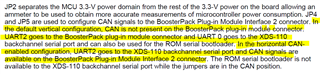
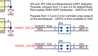
I also removed jumpers JP4 and JP5 to disconnect UART from the debugger, and connected a COM port directly to the UART2 pins (TX, RX, and GND).

However, when I run the code, the terminal does not display any output from the UARTprintf function.
For example, the line UARTprintf("Ethernet lwIP example\n\n"); does not print anything.

When I perform the same procedure using UART0 (as in the original example), the output appears correctly on the terminal.

Is there anything else I need to do to access UART2?

  • Hi,

    I also removed jumpers JP4 and JP5 to disconnect UART from the debugger,

    You don't just remove JP4 and JP5 but rather change from their default vertical orientation to horizontal orientation. Once you do that, the UART2TX and UART2RX are routed to the XDS110 debug probe for COM port. Refer to the user's guide for details. 

    2.1.6.2 BoosterPack Plug-in Module Interface 2

    The second BoosterPack XL interface is located near the bottom of the board. This interface is fully compliant with the BoosterPack plug-in module standard, and adds features not covered by the BoosterPack plug-in module standard that enable operation with additional BoosterPack plug-in modules. Using the jumpers JP4 and JP5, Controller Area Network (CAN) digital receive and transmit signals can be optionally routed to the BoosterPack Plug-in Module Interface 2 connector. In the default configuration, UART0 is used for the XDS-110 backchannel UART and CAN is not present on the BoosterPack plug-in module headers. In this configuration, the ROM serial bootloader can be used over the XDS-110 backchannel UART. When the jumpers are configured for CAN on the BoosterPack plug-in module interface, then UART2 must be used for the XDS-110 backchannel UART.

  • Hi Sir,

    In my design i am using only MCU but don't want to use debugger. So without debugger how can I access UART 2 . Right now I am directly connecting COM port to TX and RX pin of UART2 and in code i have changed parameter to 2 from 0 in UART configuration function. We want to use debugger just for programming purpose.

  • Hi,

    In my design i am using only MCU but don't want to use debugger.

    Please note that without debugger, you cannot debug your code. 

    So without debugger how can I access UART 2 .

    Are you working with a bootloader. If you are using a debugger with a JTAG interface then the only way to download or update your firmware is through some type of communication interfaces such as UART using a bootloader. Is this what you are looking to do? If UART bootloader is what you are looking into then please refer to the BSL document https://www.ti.com/lit/pdf/slau746 and https://dev.ti.com/tirex/explore/node?node=A__ADn.VTNH8qUYxgak.wnmVw__com.ti.SIMPLELINK_ACADEMY_MSP432E4SDK__Nh7md.m__LATEST

    Right now I am directly connecting COM port to TX and RX pin of UART2

    Who is your host? Is it a PC? I'm not clear what you meant that you connect the COM port directly to TX and RX of the UART2. How can you do this without a FTDI chip that acts a USB to serial bridge? 

  • Sir ,

    I am not using UART for programing MCU. In design I will use external debugger (XDS110) & JTAG to program MCU .

    But Right now my setup is that i have MCU board and using its debugger for programing and taking power form laptop through USB.

    I modified the line UARTStdioConfig(0, 115200, g_ui32SysClock) in the enet_lwip.c file of the ethernet_with_lwip_MSP-EXP432E401Y code example to UARTStdioConfig(2, 115200, g_ui32SysClock).
    to access UART2 of the microcontroller instead of UART0.

    Also i have added UARTprintf("Ethernet lwIP example\n\n")  line in a while loop, So that this data continuously transmitted by UART2.

    After above modification i build and loaded the program in MCU.

    After programing  i removed JP5 and JP4 jumpers  of MCU to avoid access of UART through debugger.

    Then I taken a USB to serial adapter and connected its USB end to laptop and its RX pin to J5-TX pin of MCU and its TX pin to J5 -RX pin of MCU.

    I opened  putty  in PC to access the data coming through UART2. But did't receive any thing.

    Same when i am doing with UART0 its showing output on putty.

    Is there any other modification  required in software to access UART2.

  • After programing  i removed JP5 and JP4 jumpers  of MCU to avoid access of UART through debugger.

    Normally, you would change the JP4/JP5 from their vertical orientation to horizontal orientation so that UART2 is routed to the integrated XDS110 on the LaunchPad. There is no need to use a separate FTDI chip from UART2 to your PC. If you want to use your own FTDI for UART2 then you need to put back the JP4 and JP4 to their vertical position. In this case, the UART0 is still connected to XDS110. 

  • Sir

    //*****************************************************************************
    //
    // enet_lwip.c - Sample WebServer Application using lwIP.
    //
    // Copyright (c) 2013-2017 Texas Instruments Incorporated.  All rights reserved.
    // Software License Agreement
    //
    // Texas Instruments (TI) is supplying this software for use solely and
    // exclusively on TI's microcontroller products. The software is owned by
    // TI and/or its suppliers, and is protected under applicable copyright
    // laws. You may not combine this software with "viral" open-source
    // software in order to form a larger program.
    //
    // THIS SOFTWARE IS PROVIDED "AS IS" AND WITH ALL FAULTS.
    // NO WARRANTIES, WHETHER EXPRESS, IMPLIED OR STATUTORY, INCLUDING, BUT
    // NOT LIMITED TO, IMPLIED WARRANTIES OF MERCHANTABILITY AND FITNESS FOR
    // A PARTICULAR PURPOSE APPLY TO THIS SOFTWARE. TI SHALL NOT, UNDER ANY
    // CIRCUMSTANCES, BE LIABLE FOR SPECIAL, INCIDENTAL, OR CONSEQUENTIAL
    // DAMAGES, FOR ANY REASON WHATSOEVER.
    //
    //
    //*****************************************************************************
    
    #include <stdbool.h>
    #include <stdint.h>
    #include "ti/devices/msp432e4/driverlib/driverlib.h"
    #include "ti/devices/msp432e4/inc/msp.h"
    #include "ustdlib.h"
    #include "uartstdio.h"
    #include "pinout.h"
    #include "locator.h"
    #include "lwiplib.h"
    #include "lwip/apps/httpd.h"
    
    #include <stdio.h>
    #include "lwip/pbuf.h"
    #include "lwip/ip_addr.h"
    #include <string.h>
    //#include "inc/hw_ints.h"
    //#include "inc/hw_memmap.h"
    //#include "driverlib/flash.h"
    //#include "driverlib/interrupt.h"
    //#include "driverlib/gpio.h"
    //#include "driverlib/rom_map.h"
    //#include "driverlib/sysctl.h"
    //#include "driverlib/systick.h"
    //#include "utils/lwiplib.h"
    //#include "utils/ustdlib.h"
    //#include "utils/uartstdio.h"
    //#include "drivers/pinout.h"
    #include "lwip/udp.h"
    #include "lwip/inet.h"
    #include "lwip/ip_addr.h"
    
    //*****************************************************************************
    //
    //! \addtogroup example_list
    //! <h1>Ethernet with lwIP (enet_lwip)</h1>
    //!
    //! This example application demonstrates the operation of the MSP432E4
    //! Ethernet controller using the lwIP TCP/IP Stack.  DHCP is used to obtain
    //! an Ethernet address.  If DHCP times out without obtaining an address,
    //! AutoIP will be used to obtain a link-local address.  The address that is
    //! selected will be shown on the UART.
    //!
    //! UART0, connected to the ICDI virtual COM port and running at 115,200,
    //! 8-N-1, is used to display messages from this application. Use the
    //! following command to re-build the any file system files that change.
    //!
    //! ../../../../../tools/examples/makefsfile/makefsfile.exe -i fs -o enet_fsdata.h -r -h -q
    //!
    //! For additional details on lwIP, refer to the lwIP web page at:
    //! http://savannah.nongnu.org/projects/lwip/
    //
    //*****************************************************************************
    
    //*****************************************************************************
    //
    // Defines for setting up the system clock.
    //
    //*****************************************************************************
    
    struct udp_pcb *pcb;
    struct udp_pcb *upcb; // Assume this is properly initialized and configured
    struct pbuf *p;
    #define SYSTICKHZ               100
    #define SYSTICKMS               (1000 / SYSTICKHZ)
    
    //*****************************************************************************
    //
    // Interrupt priority definitions.  The top 3 bits of these values are
    // significant with lower values indicating higher priority interrupts.
    //
    //*****************************************************************************
    #define SYSTICK_INT_PRIORITY    0x80
    #define ETHERNET_INT_PRIORITY   0xC0
    #define PORT                     23
    
    
    #define SERVER_IPADDR "192.168.1.5"
    #define CLIENT_PORT 23
    #define SERVER_PORT 23
    u8_t  r;
    u8_t  flag;
    //*****************************************************************************
    //
    // The current IP address.
    //
    //*****************************************************************************
    uint32_t g_ui32IPAddress;
    
    //*****************************************************************************
    //
    // The system clock frequency.
    //
    //*****************************************************************************
    uint32_t g_ui32SysClock;
    
    //*****************************************************************************
    //
    // Volatile global flag to manage LED blinking, since it is used in interrupt
    // and main application.  The LED blinks at the rate of SYSTICKHZ.
    //
    //*****************************************************************************
    volatile bool g_bLED;
    
    //*****************************************************************************
    //
    // The error routine that is called if the driver library encounters an error.
    //
    //*****************************************************************************
    #ifdef DEBUG
    void
    __error__(char *pcFilename, uint32_t ui32Line)
    {
    }
    #endif
    
    //********************************************************************************
    
    struct ip_addr {
      u32_t addr;
    };
    struct pbuf *p;
    void
    UdpClientInit(void)
    {
       ///////// struct pbuf *p;
        struct ip_addr ServerIPaddr;
      //  struct ip_addr *ServerIPaddr;
    
    
        err_t err;
        char *greeting = "Hello! Greeting from EK-TM4C129XL LaunchPad \r\n";
      //  uint8_t data[] = { 76, 69, 68, 95, 79, 78 };
    
        //
        // Create a new UDP control block.
        //
        upcb = udp_new();
    
        if (upcb!=NULL)
        {
            //
            // Bind the PCB to local address=IP_ADDR_ANY at port 23.
            // Also register the callback function to call when receiving payload.
            //
            udp_bind(upcb, IP_ADDR_ANY, CLIENT_PORT);
           // udp_recv(upcb, UdpEchoRecv, NULL);
    
            //
            // Assign destination server IP address.
            //
           // ServerIPaddr.addr = inet_addr(SERVER_IPADDR);
            ServerIPaddr.addr = inet_addr("192.168.1.5");
    
            //
            // Configure destination IP address and port.
            //
            err = udp_connect(upcb, &ServerIPaddr, SERVER_PORT);
    
            if (err == ERR_OK)
            {
                //
                // Allocate pbuf from pool.
                //
              //  p = pbuf_alloc(PBUF_TRANSPORT,strlen((char*)greeting), PBUF_RAM);
              //  p = pbuf_alloc(PBUF_TRANSPORT, sizeof(data), PBUF_RAM);
                flag=1;
    //            if (p != NULL)
    //            {
    //                //
    //                // Copy greeting to pbuf.
    //                //
    //             //   memcpy(p->payload, data, sizeof(data));
    //               // pbuf_take(p, (char*)greeting, strlen((char*)greeting));
    //
    //                //
    //                // Send the UDP data.
    //                //
    //
    //
    //               // udp_send(upcb, p);
    //
    //
    //
    //                //
    //                // Free pbuf.
    //                //
    //        /////   pbuf_free(p);
    //
    //            }
    //            else
    //            {
    //                //
    //                // Free the UDP connection, so we can accept new clients.
    //                //
    //                udp_remove(upcb);
    //                UARTprintf("\n\r can not allocate pbuf ");
    //            }
            }
            else
            {
                //
                // Free the UDP connection, so we can accept new clients.
                //
                udp_remove(upcb);
                UARTprintf("\n\r can not connect udp pcb");
            }
        }
        else
        {
            UARTprintf("\n\r can not create udp pcb");
        }
    
        //
        // Disconnect the remote address from the PCB.
        //
       ///////////////////// udp_disconnect(upcb);
    
    }
    
    //void
    //UdpEchoRecv(void *arg, struct udp_pcb *pcb, struct pbuf *p,
    //            struct ip_addr *addr, u16_t port)
    //{
    //    if (p != NULL) {
    //        //
    //        // Set global flag and print a message in main() indicating the number of
    //        // bytes that has been received from the remote host.
    //        //
    //        g_scbFlag.EchoRecv = 1;
    //        g_scbFlag.len = p->tot_len;
    //        //
    //        // Send received packet back to sender.
    //        //
    //        udp_sendto(pcb, p, addr, port);
    //
    //        //
    //        // Free the pbuf.
    //        //
    //        pbuf_free(p);
    //    }
    //}


    //
    void
    UdpEchoRecv(void *arg, struct udp_pcb *pcb, struct pbuf *b, struct
                ip_addr *addr, u16_t port)
    {
        if (b != NULL) {
            //
            // Send received packet back to sender. The udp_sendto is similar to
            // udp_send(), but sends to any remote address.
            //
            u8_t  i;
            struct pbuf *g;
    
            for(g = b; g != NULL; g = g->next) {
                    // Print the payload of each pbuf
                    for(i = 0; i < g->len; i++) {
                        UARTprintf("%c", *((char*)(g->payload + i)));
                    }
                }
            udp_sendto(pcb, b, addr, port);
    
            //
            // Free the pbuf.
            //
            pbuf_free(b);
        }
    }
    //
    //
    void
    UdpEchoInit(void)
    {
        struct udp_pcb * pcb;
    
        //
        // Get the new PCB.
        //
        pcb = udp_new();
        if (pcb == NULL) {
            UARTprintf("udp_new failed!\n");
            return;
        }
    
        //
        // Bind to any IP address on port 23.
        //
        if (udp_bind(pcb, IP_ADDR_ANY, 25) != ERR_OK) {
            UARTprintf("udp_bind failed!\n");
            return;
        }
    
        //
        // Register UdpEchoRecv() as callback function for received packets.
        //
        udp_recv(pcb, UdpEchoRecv, NULL);
    }


    //*****************************************************************************
    //
    // Display an lwIP type IP Address.
    //
    //*****************************************************************************
    void
    DisplayIPAddress(uint32_t ui32Addr)
    {
        char pcBuf[16];
    
        //
        // Convert the IP Address into a string.
        //
        usprintf(pcBuf, "%d.%d.%d.%d", ui32Addr & 0xff, (ui32Addr >> 8) & 0xff,
                (ui32Addr >> 16) & 0xff, (ui32Addr >> 24) & 0xff);
    
        //
        // Display the string.
        //
        UARTprintf(pcBuf);
    }
    
    //*****************************************************************************
    //
    // Required by lwIP library to support any host-related timer functions.
    //
    //*****************************************************************************
    void
    lwIPHostTimerHandler(void)
    {
        uint32_t ui32NewIPAddress;
    
        //
        // Get the current IP address.
        //
        ui32NewIPAddress = lwIPLocalIPAddrGet();
    
        //
        // See if the IP address has changed.
        //
        if(ui32NewIPAddress != g_ui32IPAddress)
        {
            //
            // See if there is an IP address assigned.
            //
            if(ui32NewIPAddress == 0xffffffff)
            {
                //
                // Indicate that there is no link.
                //
                UARTprintf("Waiting for link.\n");
            }
            else if(ui32NewIPAddress == 0)
            {
                //
                // There is no IP address, so indicate that the DHCP process is
                // running.
                //
                UARTprintf("Waiting for IP address.\n");
            }
            else
            {
                //
                // Display the new IP address.
                //
                UARTprintf("IP Address: ");
                DisplayIPAddress(ui32NewIPAddress);
              //  UARTprintf("\nOpen a browser and enter the IP address.\n");
            }
    
            //
            // Save the new IP address.
            //
            g_ui32IPAddress = ui32NewIPAddress;
        }
    
        //
        // If there is not an IP address.
        //
        if((ui32NewIPAddress == 0) || (ui32NewIPAddress == 0xffffffff))
        {
            //
            // Do nothing and keep waiting.
            //
        }
    }
    
    //*****************************************************************************
    //
    // The interrupt handler for the SysTick interrupt.
    //
    //*****************************************************************************
    void
    SysTick_Handler(void)
    {
        //
        // Call the lwIP timer handler.
        //
        lwIPTimer(SYSTICKMS);
    
        //
        // Tell the application to change the state of the LED (in other words
        // blink).
        //
        g_bLED = true;
    }
    
    //*****************************************************************************
    //
    // This example demonstrates the use of the Ethernet Controller.
    //
    //*****************************************************************************
    int
    main(void)
    {
        uint32_t ui32User0, ui32User1;
        uint8_t pui8MACArray[8];
    
        //
        // Make sure the main oscillator is enabled because this is required by
        // the PHY.  The system must have a 25MHz crystal attached to the OSC
        // pins. The SYSCTL_MOSC_HIGHFREQ parameter is used when the crystal
        // frequency is 10MHz or higher.
        //
        SysCtlMOSCConfigSet(SYSCTL_MOSC_HIGHFREQ);
    
        //
        // Run from the PLL at 120 MHz.
        //
        g_ui32SysClock = MAP_SysCtlClockFreqSet((SYSCTL_XTAL_25MHZ |
                                                 SYSCTL_OSC_MAIN |
                                                 SYSCTL_USE_PLL |
                                                 SYSCTL_CFG_VCO_480), 120000000);
    
        //
        // Configure the device pins.
        //
        PinoutSet(true, false);
    
        //
        // Configure UART.
        //
        UARTStdioConfig(2, 115200, g_ui32SysClock);
    
        //
        // Clear the terminal and print banner.
        //
        UARTprintf("\033[2J\033[H");
        UARTprintf("Ethernet lwIP example\n\n");
    
        //
        // Configure Port N1 for as an output for the animation LED.
        //
        MAP_GPIOPinTypeGPIOOutput(GPIO_PORTN_BASE, GPIO_PIN_1);
    
        //
        // Initialize LED to OFF (0)
        //
        MAP_GPIOPinWrite(GPIO_PORTN_BASE, GPIO_PIN_1, ~GPIO_PIN_1);
    
        //
        // Configure SysTick for a periodic interrupt.
        //
        MAP_SysTickPeriodSet(g_ui32SysClock / SYSTICKHZ);
        MAP_SysTickEnable();
        MAP_SysTickIntEnable();
    
        //
        // Configure the hardware MAC address for Ethernet Controller filtering of
        // incoming packets.  The MAC address will be stored in the non-volatile
        // USER0 and USER1 registers.
        //
        MAP_FlashUserGet(&ui32User0, &ui32User1);
        if((ui32User0 == 0xffffffff) || (ui32User1 == 0xffffffff))
        {
            //
            // We should never get here.  This is an error if the MAC address has
            // not been programmed into the device.  Exit the program.
            // Let the user know there is no MAC address
            //
            UARTprintf("No MAC programmed!\n");
            while(1)
            {
            }
        }
    
        //
        // Tell the user what we are doing just now.
        //
        UARTprintf("Waiting for IP.\n");
    
        //
        // Convert the 24/24 split MAC address from NV ram into a 32/16 split MAC
        // address needed to program the hardware registers, then program the MAC
        // address into the Ethernet Controller registers.
        //
        pui8MACArray[0] = ((ui32User0 >>  0) & 0xff);
        pui8MACArray[1] = ((ui32User0 >>  8) & 0xff);
        pui8MACArray[2] = ((ui32User0 >> 16) & 0xff);
        pui8MACArray[3] = ((ui32User1 >>  0) & 0xff);
        pui8MACArray[4] = ((ui32User1 >>  8) & 0xff);
        pui8MACArray[5] = ((ui32User1 >> 16) & 0xff);
    
        //
        // Initialize the lwIP library, using DHCP.
        //
       // lwIPInit(g_ui32SysClock, pui8MACArray, 0, 0, 0, IPADDR_USE_DHCP);
        lwIPInit(g_ui32SysClock, pui8MACArray, 3232235777, 4294967040, 0, IPADDR_USE_STATIC);
    
    
        //
         // Start the client to send a greeting message to the external host.
         //
    
        MAP_GPIOPinTypeGPIOInput(GPIO_PORTH_BASE, GPIO_PIN_1);
        r= MAP_GPIOPinRead(GPIO_PORTH_BASE, GPIO_PIN_1);
        UARTprintf("GPIO_PIN_1 %i value  ",r);
    
        MAP_GPIOPinTypeGPIOInput(GPIO_PORTH_BASE, GPIO_PIN_0);
        u8_t  n= MAP_GPIOPinRead(GPIO_PORTH_BASE, GPIO_PIN_0);
        UARTprintf(" GPIO_PIN_0 %i value  ",n);
    
        MAP_GPIOPinTypeGPIOInput(GPIO_PORTH_BASE, GPIO_PIN_2);
        u8_t  c= MAP_GPIOPinRead(GPIO_PORTH_BASE, GPIO_PIN_2);
        UARTprintf(" GPIO_PIN_2 %i value  ",c);
    
         UdpEchoInit();
         UdpClientInit();
    
       // const char *message = "Hello, World!";
       //udp_send_data(pcb, message, 11);
    
        //
        // Setup the device locator service.
        //
        LocatorInit();
        LocatorMACAddrSet(pui8MACArray);
        LocatorAppTitleSet("MSP432E4 enet_io");
    
        //
        // Initialize a sample httpd server.
        //
      //  httpd_init();
    
        //
        // Set the interrupt priorities.  We set the SysTick interrupt to a higher
        // priority than the Ethernet interrupt to ensure that the file system
        // tick is processed if SysTick occurs while the Ethernet handler is being
        // processed.  This is very likely since all the TCP/IP and HTTP work is
        // done in the context of the Ethernet interrupt.
        //
        MAP_IntPrioritySet(INT_EMAC0, ETHERNET_INT_PRIORITY);
        MAP_IntPrioritySet(FAULT_SYSTICK, SYSTICK_INT_PRIORITY);
    
        //
        // Loop forever, processing the LED blinking.  All the work is done in
        // interrupt handlers.
        //
        while(1)
        {
            //
            // Wait till the SysTick Interrupt indicates to change the state of the
            // LED.
            //
            while(g_bLED == false)
            {
            }
    
            //
            // Clear the flag.
            //
            g_bLED = false;
    
            //
            // Toggle the LED.
            //
            MAP_GPIOPinWrite(GPIO_PORTN_BASE, GPIO_PIN_1,
                             (MAP_GPIOPinRead(GPIO_PORTN_BASE, GPIO_PIN_1) ^
                              GPIO_PIN_1));
    
            MAP_GPIOPinTypeGPIOInput(GPIO_PORTH_BASE, GPIO_PIN_1);
               r= MAP_GPIOPinRead(GPIO_PORTH_BASE, GPIO_PIN_1);
            //   UARTprintf("GPIO_PIN_1 %i value  ",r);
    
    
                   if(r)
                   {
                   ROM_GPIOPinTypeGPIOOutput(GPIO_PORTN_BASE, GPIO_PIN_0 | GPIO_PIN_1);
                       MAP_GPIOPadConfigSet(GPIO_PORTN_BASE, GPIO_PIN_0 | GPIO_PIN_1,
                                                GPIO_STRENGTH_12MA, GPIO_PIN_TYPE_STD);
    
                       if(flag==1)
                      {
                       ROM_GPIOPinWrite(GPIO_PORTN_BASE, GPIO_PIN_0 | GPIO_PIN_1, 1);
                       uint8_t data1[] = { 76, 69, 68, 95, 79, 78 };
                       p = pbuf_alloc(PBUF_TRANSPORT, sizeof(data1), PBUF_RAM);
                       memcpy(p->payload, data1, sizeof(data1));
    
                       udp_send(upcb, p);
                       UARTprintf("flag %i value  ",flag);
                       flag=0;
                       }
    
                      // UdpClientInit();
                   }
    
                   if(!r)
                               {
                               ROM_GPIOPinTypeGPIOOutput(GPIO_PORTN_BASE, GPIO_PIN_0 | GPIO_PIN_1);
                                   MAP_GPIOPadConfigSet(GPIO_PORTN_BASE, GPIO_PIN_0 | GPIO_PIN_1,
                                                            GPIO_STRENGTH_12MA, GPIO_PIN_TYPE_STD);
    
                                   //
                                   //
                                   //
                                   ROM_GPIOPinWrite(GPIO_PORTN_BASE, GPIO_PIN_0 | GPIO_PIN_1, 0);
                                   pbuf_free(p);
                                   flag=1;
                               }
    
    
        }
    }

    I tried to access UART2 through XDS110  by changing the JP4/JP5 from their vertical orientation to horizontal orientation . Still I  am not able to get prints on putty terminal. Is there any other parameter in code i need to change . Till know i have modified the line UARTStdioConfig(0, 115200, g_ui32SysClock) in the enet_lwip.c file of the ethernet_with_lwip_MSP-EXP432E401Y code example to UARTStdioConfig(2, 115200, g_ui32SysClock).

  • Below is what you have in your code. The problem is that in PinoutSet() it only configures UART0, not UART2. You would need to change it for UART2. 

    //
    // Configure the device pins.
    //
    PinoutSet(true, false);

    //
    // Configure UART.
    //
    UARTStdioConfig(2, 115200, g_ui32SysClock);

    Why don't you write like below to configure UART2 before you call UARTStdioConfig(2, 115200, g_ui32SysClock). 

    SysCtlPeripheralEnable(SYSCTL_PERIPH_GPIOD);
    SysCtlPeripheralEnable(SYSCTL_PERIPH_UART2);
    GPIOPinConfigure(GPIO_PD4_U2RX);
    GPIOPinConfigure(GPIO_PD5_U2TX);
    GPIOPinTypeUART(GPIO_PORTD_BASE, GPIO_PIN_4 | GPIO_PIN_5);
    UARTStdioConfig(2, 115200, g_ui32SysClock);

  • //*****************************************************************************
    //
    // enet_lwip.c - Sample WebServer Application using lwIP.
    //
    // Copyright (c) 2013-2017 Texas Instruments Incorporated.  All rights reserved.
    // Software License Agreement
    //
    // Texas Instruments (TI) is supplying this software for use solely and
    // exclusively on TI's microcontroller products. The software is owned by
    // TI and/or its suppliers, and is protected under applicable copyright
    // laws. You may not combine this software with "viral" open-source
    // software in order to form a larger program.
    //
    // THIS SOFTWARE IS PROVIDED "AS IS" AND WITH ALL FAULTS.
    // NO WARRANTIES, WHETHER EXPRESS, IMPLIED OR STATUTORY, INCLUDING, BUT
    // NOT LIMITED TO, IMPLIED WARRANTIES OF MERCHANTABILITY AND FITNESS FOR
    // A PARTICULAR PURPOSE APPLY TO THIS SOFTWARE. TI SHALL NOT, UNDER ANY
    // CIRCUMSTANCES, BE LIABLE FOR SPECIAL, INCIDENTAL, OR CONSEQUENTIAL
    // DAMAGES, FOR ANY REASON WHATSOEVER.
    //
    //
    //*****************************************************************************
    
    #include <stdbool.h>
    #include <stdint.h>
    #include "ti/devices/msp432e4/driverlib/driverlib.h"
    #include "ti/devices/msp432e4/inc/msp.h"
    #include "ustdlib.h"
    #include "uartstdio.h"
    #include "pinout.h"
    #include "locator.h"
    #include "lwiplib.h"
    #include "lwip/apps/httpd.h"
    
    #include <stdio.h>
    #include "lwip/pbuf.h"
    #include "lwip/ip_addr.h"
    #include <string.h>
    //#include "inc/hw_ints.h"
    //#include "inc/hw_memmap.h"
    //#include "driverlib/flash.h"
    //#include "driverlib/interrupt.h"
    //#include "driverlib/gpio.h"
    //#include "driverlib/rom_map.h"
    //#include "driverlib/sysctl.h"
    //#include "driverlib/systick.h"
    //#include "utils/lwiplib.h"
    //#include "utils/ustdlib.h"
    //#include "utils/uartstdio.h"
    //#include "drivers/pinout.h"
    #include "lwip/udp.h"
    #include "lwip/inet.h"
    #include "lwip/ip_addr.h"
    
    //*****************************************************************************
    //
    //! \addtogroup example_list
    //! <h1>Ethernet with lwIP (enet_lwip)</h1>
    //!
    //! This example application demonstrates the operation of the MSP432E4
    //! Ethernet controller using the lwIP TCP/IP Stack.  DHCP is used to obtain
    //! an Ethernet address.  If DHCP times out without obtaining an address,
    //! AutoIP will be used to obtain a link-local address.  The address that is
    //! selected will be shown on the UART.
    //!
    //! UART0, connected to the ICDI virtual COM port and running at 115,200,
    //! 8-N-1, is used to display messages from this application. Use the
    //! following command to re-build the any file system files that change.
    //!
    //! ../../../../../tools/examples/makefsfile/makefsfile.exe -i fs -o enet_fsdata.h -r -h -q
    //!
    //! For additional details on lwIP, refer to the lwIP web page at:
    //! http://savannah.nongnu.org/projects/lwip/
    //
    //*****************************************************************************
    
    //*****************************************************************************
    //
    // Defines for setting up the system clock.
    //
    //*****************************************************************************
    
    struct udp_pcb *pcb;
    struct udp_pcb *upcb; // Assume this is properly initialized and configured
    struct pbuf *p;
    #define SYSTICKHZ               100
    #define SYSTICKMS               (1000 / SYSTICKHZ)
    
    //*****************************************************************************
    //
    // Interrupt priority definitions.  The top 3 bits of these values are
    // significant with lower values indicating higher priority interrupts.
    //
    //*****************************************************************************
    #define SYSTICK_INT_PRIORITY    0x80
    #define ETHERNET_INT_PRIORITY   0xC0
    #define PORT                     23
    
    
    #define SERVER_IPADDR "192.168.1.5"
    #define CLIENT_PORT 23
    #define SERVER_PORT 23
    u8_t  r;
    u8_t  flag;
    //*****************************************************************************
    //
    // The current IP address.
    //
    //*****************************************************************************
    uint32_t g_ui32IPAddress;
    
    //*****************************************************************************
    //
    // The system clock frequency.
    //
    //*****************************************************************************
    uint32_t g_ui32SysClock;
    
    //*****************************************************************************
    //
    // Volatile global flag to manage LED blinking, since it is used in interrupt
    // and main application.  The LED blinks at the rate of SYSTICKHZ.
    //
    //*****************************************************************************
    volatile bool g_bLED;
    
    //*****************************************************************************
    //
    // The error routine that is called if the driver library encounters an error.
    //
    //*****************************************************************************
    #ifdef DEBUG
    void
    __error__(char *pcFilename, uint32_t ui32Line)
    {
    }
    #endif
    
    //********************************************************************************
    
    struct ip_addr {
      u32_t addr;
    };
    struct pbuf *p;
    void
    UdpClientInit(void)
    {
       ///////// struct pbuf *p;
        struct ip_addr ServerIPaddr;
      //  struct ip_addr *ServerIPaddr;
    
    
        err_t err;
        char *greeting = "Hello! Greeting from EK-TM4C129XL LaunchPad \r\n";
      //  uint8_t data[] = { 76, 69, 68, 95, 79, 78 };
    
        //
        // Create a new UDP control block.
        //
        upcb = udp_new();
    
        if (upcb!=NULL)
        {
            //
            // Bind the PCB to local address=IP_ADDR_ANY at port 23.
            // Also register the callback function to call when receiving payload.
            //
            udp_bind(upcb, IP_ADDR_ANY, CLIENT_PORT);
           // udp_recv(upcb, UdpEchoRecv, NULL);
    
            //
            // Assign destination server IP address.
            //
           // ServerIPaddr.addr = inet_addr(SERVER_IPADDR);
            ServerIPaddr.addr = inet_addr("192.168.1.5");
    
            //
            // Configure destination IP address and port.
            //
            err = udp_connect(upcb, &ServerIPaddr, SERVER_PORT);
    
            if (err == ERR_OK)
            {
                //
                // Allocate pbuf from pool.
                //
              //  p = pbuf_alloc(PBUF_TRANSPORT,strlen((char*)greeting), PBUF_RAM);
              //  p = pbuf_alloc(PBUF_TRANSPORT, sizeof(data), PBUF_RAM);
                flag=1;
    //            if (p != NULL)
    //            {
    //                //
    //                // Copy greeting to pbuf.
    //                //
    //             //   memcpy(p->payload, data, sizeof(data));
    //               // pbuf_take(p, (char*)greeting, strlen((char*)greeting));
    //
    //                //
    //                // Send the UDP data.
    //                //
    //
    //
    //               // udp_send(upcb, p);
    //
    //
    //
    //                //
    //                // Free pbuf.
    //                //
    //        /////   pbuf_free(p);
    //
    //            }
    //            else
    //            {
    //                //
    //                // Free the UDP connection, so we can accept new clients.
    //                //
    //                udp_remove(upcb);
    //                UARTprintf("\n\r can not allocate pbuf ");
    //            }
            }
            else
            {
                //
                // Free the UDP connection, so we can accept new clients.
                //
                udp_remove(upcb);
                UARTprintf("\n\r can not connect udp pcb");
            }
        }
        else
        {
            UARTprintf("\n\r can not create udp pcb");
        }
    
        //
        // Disconnect the remote address from the PCB.
        //
       ///////////////////// udp_disconnect(upcb);
    
    }
    
    //void
    //UdpEchoRecv(void *arg, struct udp_pcb *pcb, struct pbuf *p,
    //            struct ip_addr *addr, u16_t port)
    //{
    //    if (p != NULL) {
    //        //
    //        // Set global flag and print a message in main() indicating the number of
    //        // bytes that has been received from the remote host.
    //        //
    //        g_scbFlag.EchoRecv = 1;
    //        g_scbFlag.len = p->tot_len;
    //        //
    //        // Send received packet back to sender.
    //        //
    //        udp_sendto(pcb, p, addr, port);
    //
    //        //
    //        // Free the pbuf.
    //        //
    //        pbuf_free(p);
    //    }
    //}


    //
    void
    UdpEchoRecv(void *arg, struct udp_pcb *pcb, struct pbuf *b, struct
                ip_addr *addr, u16_t port)
    {
        if (b != NULL) {
            //
            // Send received packet back to sender. The udp_sendto is similar to
            // udp_send(), but sends to any remote address.
            //
            u8_t  i;
            struct pbuf *g;
    
            for(g = b; g != NULL; g = g->next) {
                    // Print the payload of each pbuf
                    for(i = 0; i < g->len; i++) {
                        UARTprintf("%c", *((char*)(g->payload + i)));
                    }
                }
            udp_sendto(pcb, b, addr, port);
    
            //
            // Free the pbuf.
            //
            pbuf_free(b);
        }
    }
    //
    //
    void
    UdpEchoInit(void)
    {
        struct udp_pcb * pcb;
    
        //
        // Get the new PCB.
        //
        pcb = udp_new();
        if (pcb == NULL) {
            UARTprintf("udp_new failed!\n");
            return;
        }
    
        //
        // Bind to any IP address on port 23.
        //
        if (udp_bind(pcb, IP_ADDR_ANY, 25) != ERR_OK) {
            UARTprintf("udp_bind failed!\n");
            return;
        }
    
        //
        // Register UdpEchoRecv() as callback function for received packets.
        //
        udp_recv(pcb, UdpEchoRecv, NULL);
    }


    //*****************************************************************************
    //
    // Display an lwIP type IP Address.
    //
    //*****************************************************************************
    void
    DisplayIPAddress(uint32_t ui32Addr)
    {
        char pcBuf[16];
    
        //
        // Convert the IP Address into a string.
        //
        usprintf(pcBuf, "%d.%d.%d.%d", ui32Addr & 0xff, (ui32Addr >> 8) & 0xff,
                (ui32Addr >> 16) & 0xff, (ui32Addr >> 24) & 0xff);
    
        //
        // Display the string.
        //
        UARTprintf(pcBuf);
    }
    
    //*****************************************************************************
    //
    // Required by lwIP library to support any host-related timer functions.
    //
    //*****************************************************************************
    void
    lwIPHostTimerHandler(void)
    {
        uint32_t ui32NewIPAddress;
    
        //
        // Get the current IP address.
        //
        ui32NewIPAddress = lwIPLocalIPAddrGet();
    
        //
        // See if the IP address has changed.
        //
        if(ui32NewIPAddress != g_ui32IPAddress)
        {
            //
            // See if there is an IP address assigned.
            //
            if(ui32NewIPAddress == 0xffffffff)
            {
                //
                // Indicate that there is no link.
                //
                UARTprintf("Waiting for link.\n");
            }
            else if(ui32NewIPAddress == 0)
            {
                //
                // There is no IP address, so indicate that the DHCP process is
                // running.
                //
                UARTprintf("Waiting for IP address.\n");
            }
            else
            {
                //
                // Display the new IP address.
                //
                UARTprintf("IP Address: ");
                DisplayIPAddress(ui32NewIPAddress);
              //  UARTprintf("\nOpen a browser and enter the IP address.\n");
            }
    
            //
            // Save the new IP address.
            //
            g_ui32IPAddress = ui32NewIPAddress;
        }
    
        //
        // If there is not an IP address.
        //
        if((ui32NewIPAddress == 0) || (ui32NewIPAddress == 0xffffffff))
        {
            //
            // Do nothing and keep waiting.
            //
        }
    }
    
    //*****************************************************************************
    //
    // The interrupt handler for the SysTick interrupt.
    //
    //*****************************************************************************
    void
    SysTick_Handler(void)
    {
        //
        // Call the lwIP timer handler.
        //
        lwIPTimer(SYSTICKMS);
    
        //
        // Tell the application to change the state of the LED (in other words
        // blink).
        //
        g_bLED = true;
    }
    
    //*****************************************************************************
    //
    // This example demonstrates the use of the Ethernet Controller.
    //
    //*****************************************************************************
    int
    main(void)
    {
        uint32_t ui32User0, ui32User1;
        uint8_t pui8MACArray[8];
    
        //
        // Make sure the main oscillator is enabled because this is required by
        // the PHY.  The system must have a 25MHz crystal attached to the OSC
        // pins. The SYSCTL_MOSC_HIGHFREQ parameter is used when the crystal
        // frequency is 10MHz or higher.
        //
        SysCtlMOSCConfigSet(SYSCTL_MOSC_HIGHFREQ);
    
        //
        // Run from the PLL at 120 MHz.
        //
        g_ui32SysClock = MAP_SysCtlClockFreqSet((SYSCTL_XTAL_25MHZ |
                                                 SYSCTL_OSC_MAIN |
                                                 SYSCTL_USE_PLL |
                                                 SYSCTL_CFG_VCO_480), 120000000);
    
        //
        // Configure the device pins.
        //
        PinoutSet(true, false);
    
        //
        // Configure UART.
        //
    
    
        ///////////////////////////////////////////////////////////////////////////////
        UARTStdioConfig(0, 115200, g_ui32SysClock);
        ////////////////////////////////////////////////////////////////////
          SysCtlPeripheralEnable(SYSCTL_PERIPH_UART2);
          ROM_GPIOPinConfigure(GPIO_PD4_U2RX);
          ROM_GPIOPinConfigure(GPIO_PD5_U2TX);
          ROM_GPIOPinTypeUART(GPIO_PORTD_BASE, GPIO_PIN_4 | GPIO_PIN_5);
         ///////////////////////////////////////////////////////////////
        UARTStdioConfig(2, 115200, g_ui32SysClock);
    
        ////////////////////////////////////////////////////////////////////////////
        //
        // Clear the terminal and print banner.
        //
        UARTprintf("\033[2J\033[H");
        UARTprintf("Ethernet lwIP example\n\n");
    
        //
        // Configure Port N1 for as an output for the animation LED.
        //
        MAP_GPIOPinTypeGPIOOutput(GPIO_PORTN_BASE, GPIO_PIN_1);
    
        //
        // Initialize LED to OFF (0)
        //
        MAP_GPIOPinWrite(GPIO_PORTN_BASE, GPIO_PIN_1, ~GPIO_PIN_1);
    
        //
        // Configure SysTick for a periodic interrupt.
        //
        MAP_SysTickPeriodSet(g_ui32SysClock / SYSTICKHZ);
        MAP_SysTickEnable();
        MAP_SysTickIntEnable();
    
        //
        // Configure the hardware MAC address for Ethernet Controller filtering of
        // incoming packets.  The MAC address will be stored in the non-volatile
        // USER0 and USER1 registers.
        //
        MAP_FlashUserGet(&ui32User0, &ui32User1);
        if((ui32User0 == 0xffffffff) || (ui32User1 == 0xffffffff))
        {
            //
            // We should never get here.  This is an error if the MAC address has
            // not been programmed into the device.  Exit the program.
            // Let the user know there is no MAC address
            //
            UARTprintf("No MAC programmed!\n");
            while(1)
            {
            }
        }
    
        //
        // Tell the user what we are doing just now.
        //
        UARTprintf("Waiting for IP.\n");
    
        //
        // Convert the 24/24 split MAC address from NV ram into a 32/16 split MAC
        // address needed to program the hardware registers, then program the MAC
        // address into the Ethernet Controller registers.
        //
        pui8MACArray[0] = ((ui32User0 >>  0) & 0xff);
        pui8MACArray[1] = ((ui32User0 >>  8) & 0xff);
        pui8MACArray[2] = ((ui32User0 >> 16) & 0xff);
        pui8MACArray[3] = ((ui32User1 >>  0) & 0xff);
        pui8MACArray[4] = ((ui32User1 >>  8) & 0xff);
        pui8MACArray[5] = ((ui32User1 >> 16) & 0xff);
    
        //
        // Initialize the lwIP library, using DHCP.
        //
       // lwIPInit(g_ui32SysClock, pui8MACArray, 0, 0, 0, IPADDR_USE_DHCP);
        lwIPInit(g_ui32SysClock, pui8MACArray, 3232235777, 4294967040, 0, IPADDR_USE_STATIC);
    
    
        //
         // Start the client to send a greeting message to the external host.
         //
    
        MAP_GPIOPinTypeGPIOInput(GPIO_PORTH_BASE, GPIO_PIN_1);
        r= MAP_GPIOPinRead(GPIO_PORTH_BASE, GPIO_PIN_1);
        UARTprintf("GPIO_PIN_1 %i value  ",r);
    
        MAP_GPIOPinTypeGPIOInput(GPIO_PORTH_BASE, GPIO_PIN_0);
        u8_t  n= MAP_GPIOPinRead(GPIO_PORTH_BASE, GPIO_PIN_0);
        UARTprintf(" GPIO_PIN_0 %i value  ",n);
    
        MAP_GPIOPinTypeGPIOInput(GPIO_PORTH_BASE, GPIO_PIN_2);
        u8_t  c= MAP_GPIOPinRead(GPIO_PORTH_BASE, GPIO_PIN_2);
        UARTprintf(" GPIO_PIN_2 %i value  ",c);
    
         UdpEchoInit();
         UdpClientInit();
    
       // const char *message = "Hello, World!";
       //udp_send_data(pcb, message, 11);
    
        //
        // Setup the device locator service.
        //
        LocatorInit();
        LocatorMACAddrSet(pui8MACArray);
        LocatorAppTitleSet("MSP432E4 enet_io");
    
        //
        // Initialize a sample httpd server.
        //
      //  httpd_init();
    
        //
        // Set the interrupt priorities.  We set the SysTick interrupt to a higher
        // priority than the Ethernet interrupt to ensure that the file system
        // tick is processed if SysTick occurs while the Ethernet handler is being
        // processed.  This is very likely since all the TCP/IP and HTTP work is
        // done in the context of the Ethernet interrupt.
        //
        MAP_IntPrioritySet(INT_EMAC0, ETHERNET_INT_PRIORITY);
        MAP_IntPrioritySet(FAULT_SYSTICK, SYSTICK_INT_PRIORITY);
    
        //
        // Loop forever, processing the LED blinking.  All the work is done in
        // interrupt handlers.
        //
        while(1)
        {
            //
            // Wait till the SysTick Interrupt indicates to change the state of the
            // LED.
            //
    
    
            ROM_GPIOPinTypeGPIOOutput(GPIO_PORTN_BASE, GPIO_PIN_0 | GPIO_PIN_1);
                                          MAP_GPIOPadConfigSet(GPIO_PORTN_BASE, GPIO_PIN_0 | GPIO_PIN_1,
                                                                   GPIO_STRENGTH_12MA, GPIO_PIN_TYPE_STD);
    
                                          //
                                          //
                                          //
                                          ROM_GPIOPinWrite(GPIO_PORTN_BASE, GPIO_PIN_0 | GPIO_PIN_1, 1);
    
                                          UARTprintf("\n\r led on d2 ");
    
    
            while(g_bLED == false)
            {
            }
    
            //
            // Clear the flag.
            //
            g_bLED = false;
    
            //
            // Toggle the LED.
            //
            MAP_GPIOPinWrite(GPIO_PORTN_BASE, GPIO_PIN_1,
                             (MAP_GPIOPinRead(GPIO_PORTN_BASE, GPIO_PIN_1) ^
                              GPIO_PIN_1));
    
            MAP_GPIOPinTypeGPIOInput(GPIO_PORTH_BASE, GPIO_PIN_1);
               r= MAP_GPIOPinRead(GPIO_PORTH_BASE, GPIO_PIN_1);
            //   UARTprintf("GPIO_PIN_1 %i value  ",r);
    
    
                   if(r)
                   {
                   ROM_GPIOPinTypeGPIOOutput(GPIO_PORTN_BASE, GPIO_PIN_0 | GPIO_PIN_1);
                       MAP_GPIOPadConfigSet(GPIO_PORTN_BASE, GPIO_PIN_0 | GPIO_PIN_1,
                                                GPIO_STRENGTH_12MA, GPIO_PIN_TYPE_STD);
    
                       if(flag==1)
                      {
                       ROM_GPIOPinWrite(GPIO_PORTN_BASE, GPIO_PIN_0 | GPIO_PIN_1, 1);
                       uint8_t data1[] = { 76, 69, 68, 95, 79, 78 };
                       p = pbuf_alloc(PBUF_TRANSPORT, sizeof(data1), PBUF_RAM);
                       memcpy(p->payload, data1, sizeof(data1));
    
                       udp_send(upcb, p);
                       UARTprintf("flag %i value  ",flag);
                       flag=0;
                       }
    
                      // UdpClientInit();
                   }
    
                   if(!r)
                               {
                               ROM_GPIOPinTypeGPIOOutput(GPIO_PORTN_BASE, GPIO_PIN_0 | GPIO_PIN_1);
                                   MAP_GPIOPadConfigSet(GPIO_PORTN_BASE, GPIO_PIN_0 | GPIO_PIN_1,
                                                            GPIO_STRENGTH_12MA, GPIO_PIN_TYPE_STD);
    
                                   //
                                   //
                                   //
                                   ROM_GPIOPinWrite(GPIO_PORTN_BASE, GPIO_PIN_0 | GPIO_PIN_1, 0);
                                   pbuf_free(p);
                                   flag=1;
                               }
    
    
        }
    }

    Hi Sir,

    After adding above written lines in code , I am able to access UART2.

    Right now at a particular time I am able to access either UART0 or UART2 depending on what parameter i enter in line UARTStdioConfig(2, 115200, g_ui32SysClock) at the end .

    My question is what changes i need to do to access both UART simultaneously . Do I need to set parameter in line UARTStdioConfig(2 or 0, 115200, g_ui32SysClock) each time I send data.

    For example I want to transmit two different types of data through UART0 and UART2 simultaneously .

  • My question is what changes i need to do to access both UART simultaneously . Do I need to set parameter in line UARTStdioConfig(2 or 0, 115200, g_ui32SysClock) each time I send data.

    If you want to use the integrated XDS110 debug probe on the LaunchPad as a USB to Serial converter then you can only use either UART0 or UART2 one at a time. Refer to the LaunchPad schematic. See below. The TARGET_RXD and TARGET_TXD go to the XDS110. The JP4 and JP5 acts as multiplexers to select either PA0 and PA1 for UART0 or PD4 and PD5 for UART2. If you want to use both UART0 and UART2 at the same time then you can use UARTStdioConfig for UART0 and then duplicate the UARTStdioConfig function such as UARTStdioConfig2. For UART2, you need to externally use a FTDI USB to Serial converter. You can also use the UART API to send/receive to any UART instance. Use the C:\ti\simplelink_msp432e4_sdk_4_20_00_12\examples\nortos\MSP_EXP432E401Y\driverlib\uart_echo to see how to send/receive to the UART.