Other Parts Discussed in Thread: TMDSCNCD263P, UNIFLASH, SYSCONFIG
Tool/software:
Hi,
My customer is evaluating their custom board using AM263P4.
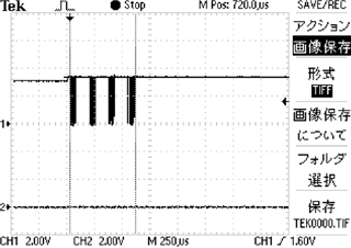
They have an issue with OSPI boot.
There is one difference between their custom board and TI control card (TMDSCNCD263P).
The customer uses IS25LX256-JHLE, but the control card uses IS25LX256-LHLE.
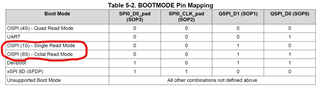
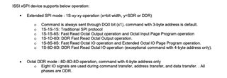
The 'L' device supports Read while Program/Erase.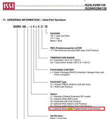
Is the "Read while Program/Erase" is mandatory for OSPI boot?
Thanks and regards,
Koichiro Tashiro