This thread has been locked.

If you have a related question, please click the "Ask a related question" button in the top right corner. The newly created question will be automatically linked to this question.

LP-MSPM0G3507: LP-MSPM0G3507

Part Number: LP-MSPM0G3507
Other Parts Discussed in Thread: MSPM0G3507, MSPM0-SDK

Tool/software:

Hello, 

I am working with custom  bootloader of MSPM0G3507. This bootloader implemented using UART and doing crc nd version check before writing new hex to flash.

In my bootloader application upon reset bootloader runs first then checks for the application at desired location presented or not if present then jump to that app if not then runs normal bootloader code.

At last if full crc of received code and calculated local crc match then it will make a jump to new application which is flashed but the issue was when i make a jump through my jump function,interrupts of jumped application not worked, it will reset the uc and start from the bootloader app at 0. as i mentioned it will check and jump to the app again.

so the main error is my interrupt handler never get executed and never wrtie bootcmd(1 at flash loc 0x0001F058 ). it wil repeat every time when interrupt i give gpio interrupt.

so can anybody help me with this beacause i am not able to find this issue and this was my first bootloader code. i attach the jump function and irq handler also linker file.
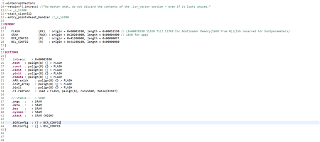
  

Linker Command File

#include "ti_msp_dl_config.h"
#include "string.h"
#include "stdio.h"
#include "core_cm0plus.h"

#define BOOTLOADER_VECTOR_TABLE_ADDRESS  0x00000000
#define BOOTLOADER_INT_LOCATION          0x0001F058 /* At this location flag set by applicant who wish to turn on boot mode to flesh nex hex */
#define VTOR_OFFSET                      (uint32_t *)0x00003E80
#define NO_ERROR                    0
#define ERROR_WRITE_32_BIT          6

void jump_to_app(uint32_t);
uint8_t BootCmdWrite(uint32_t);

volatile uint8_t gErrorType = NO_ERROR;
volatile DL_FLASHCTL_COMMAND_STATUS gCmdStatus;
uint32_t gCmd32 = 0x00000001;
uint32_t gCmdTemp;

int main(void) {

    //early_irq_enable();

    SYSCFG_DL_init();
    SCB->VTOR = (uint32_t)VTOR_OFFSET;
    __enable_irq();
    NVIC_ClearPendingIRQ(USR_BOOT_INT_IRQN);
    NVIC_EnableIRQ(USR_BOOT_INT_IRQN);

    while (1) {
        DL_GPIO_togglePins(USER_LED_PORT, USER_LED_RED_LED_PIN);
        delay_cycles(16000000);
    }
}
void GROUP1_IRQHandler(void)
{
    switch (DL_Interrupt_getPendingGroup(DL_INTERRUPT_GROUP_1)) {
        case USR_BOOT_INT_IIDX:
            /* If SW is high, turn the LED off */
            if (DL_GPIO_readPins(USR_BOOT_PORT, USR_BOOT_BT_PIN_PIN)) {
                BootCmdWrite(gCmd32);
                DL_GPIO_togglePins(RGB_PORT, RGB_GREEN_LED_PIN);
                delay_cycles(64000000);
                jump_to_app(BOOTLOADER_VECTOR_TABLE_ADDRESS);
//              NVIC_SystemReset();
            }
            break;
        default :
            break;
    }
}

uint8_t BootCmdWrite(uint32_t cmd) {
    if (gErrorType == NO_ERROR) {

        DL_FlashCTL_unprotectSector(FLASHCTL, BOOTLOADER_INT_LOCATION, DL_FLASHCTL_REGION_SELECT_MAIN);
//        gCmdStatus = DL_FlashCTL_programMemoryFromRAM64WithECCGenerated(
//                                   FLASHCTL, BOOTLOADER_INT_LOCATION, &cmd32[0]);
        DL_FlashCTL_programMemoryFromRAM32WithECCGenerated(
                                        FLASHCTL, BOOTLOADER_INT_LOCATION, &cmd);
        // Ensure write is fully committed
        __DSB();  // Data Synchronization Barrier
        __ISB();  // Instruction Synchronization Barrier
        if (gCmdStatus == DL_FLASHCTL_COMMAND_STATUS_FAILED)
        {
            /* If command was not successful, set error flag */
            gErrorType = ERROR_WRITE_32_BIT;
        }
        DL_FlashCTL_protectSector(FLASHCTL, BOOTLOADER_INT_LOCATION, DL_FLASHCTL_REGION_SELECT_MAIN);
        gCmdTemp  = *(uint32_t *)BOOTLOADER_INT_LOCATION;

    }
    return gErrorType;
}

void HardFault_Handler(void)
{
    // Debug indicator - blink LED or breakpoint
    while (1)
    {
        DL_GPIO_togglePins(RGB_PORT, RGB_GREEN_LED_PIN);
        for (volatile int i = 0; i < 100000; i++); // Simple delay
    }
}

void jump_to_app(uint32_t app_addr) {

   __disable_irq();
   // Disable and clear all interrupts
    for (uint32_t i = 0; i < 8; i++) {
        NVIC->ICER[i] = 0xFFFFFFFF;  // Disable IRQs
        NVIC->ICPR[i] = 0xFFFFFFFF;  // Clear pending IRQs
    }
       __DSB();
       __ISB();

    // Reset SysTick just in case
    SysTick->CTRL = 0;
    SysTick->LOAD = 0;
    SysTick->VAL = 0;

    uint32_t sp = *((uint32_t *)app_addr);         // Stack pointer
    uint32_t reset = *((uint32_t *)(app_addr + 4)); // Reset handler

    __set_MSP(sp);
    SCB->VTOR = app_addr;  // If needed


    ((void (*)(void))reset)(); // Jump to reset handler
}

  • Hello Helic,

    Setting VTOR in my app is same as in boot application but the difference is in my source code jump function defination present in seperate .c file not in main, it will cause any problem while setting the VTOR?

  • I don't think so, there are also other function used in other .c file.

    You can try to modify you project structure as same as boot application one.

  • Thanks But this will be time taking if you find anything related to this pls let me know.

  • guide me where to start as its tricky to understand the boot application example code, how it fetches the details? then able to jump to application.

  • Hello helic,

    I think as per function and validation of image in boot application after all this it makes the jump to application directly through address so in my case my appilcation validation happens through UART and i puts the checks before jump so indirectly process was the same but how to validate the image was different so where i am wrong if i have to modify my code as per boot application?

  • After seeing bootapplication example is there any slots in MSPM0G3507 ? used in example but not mention anything about this in reference manual.

    1) Also In example they Assign FLASH = 0x5900 in linker command file, but when at the time of load they mention to flash at 0x5800 so why this 256 bytes gap?

    2) is there any header for processiing the boot application or every bin file has the header and reset handler after 256bytes?

    3) My main question is why boot application example code able to write VTOR to 5900 but in my application not able to write the VTOR to 3E80 despite using the same function, any additional care taken in boot application example to write VTOR? 

  • Here is boot application guidance:

    https://dev.ti.com/tirex/explore/node?node=A__APjkYg9RWxwM6nRUc3InzA__MSPM0-SDK__a3PaaoK__LATEST

    1) Also In example they Assign FLASH = 0x5900 in linker command file, but when at the time of load they mention to flash at 0x5800 so why this 256 bytes gap?

    It keeps 0x100 length of Flash for MCUBOOT head.

    Building the image will require several modifications to a standard linker file: * The start of the flash will need to be considered as the beginning of the image slot plus the header offset. For example, if the primary image slot starts at 0x5400, and the mcuboot header is of size 0x100, the first element of flash of the application (the interrupt vector table) should be at address 0x5500.

    2) is there any header for processiing the boot application or every bin file has the header and reset handler after 256bytes?

    Every part of code should has a group of int vector.

    3) My main question is why boot application example code able to write VTOR to 5900 but in my application not able to write the VTOR to 3E80 despite using the same function, any additional care taken in boot application example to write VTOR? 

    From my previous experience, there is nothing need to pay attention.

    You can refer to this register for privilege mode debug:

    https://developer.arm.com/documentation/dui0662/b/The-Cortex-M0--Processor/Programmers-model/Core-registers

    CONTROL register
    The CONTROL register controls the stack used, and the optional privilege level for software execution, when the processor is in Thread mode. See the register summary in Table 2.2 for its attributes. The bit assignments are:

  • Thank you For your suggestion.

    my Issue got Resolved by doing this steps below

    1) setting my custom bootloader and application project linker file same as boot application and bim example.

    2) also i add the post build step to my custom bootloader which is present in boot application example code.

    3) erase MAIN and NONMAIN memory necessary sectors only in debug setting(Protect from erasing memory when start debug)

    But i Test one thing i tried to set the the linker files for both as below and code did not work but always work for 0x5900

    BootLoader Linker File

    FLASH = 0x0, length = 0x3200(12.8Kb)

    Application Linker File(Firmware which flashed using boot)

    FLASH = 0x32C8, length = 0x 1 BD50 (114Kb)

    and remaining 1kb reserved for verification parameter But my code did not work and behave same previous

    Question is

    1) So why this happens?

    2) As per reference manual Flash size is 128kb then why in boot application example code length = 0x0002 0000 (Nearly 131Kb)?

    3) It is possible that bootloader length should be large enough to fit the other application which will be flashing via bootloader and then only we can set the VTOR if flashed app present in bootloader region(valid region know to bootloader)?

    4) Is there any rule that you must have to specifiy address in multiple of 128?

    I think my post build step may be the cause of this

  • I did test of setting the VTOR with address which is multiple of 128 and all this address successfully written to VTOR every time.

    so the conclusion is the VTOR only support address which is multiple of 128

    Now Im thinking of remove all the above mention things i do as per example code of BIM and boot in my code so i can find what is neccessary to do run my custom boot loader and app smoothly and cause of using this steps in example one by one.

    Also i need clearification question i asked if you know please,

    Your suggestion really help me to find the solution.

    thanks you helic.

    waiting for clearification and answers 

  • 1) So why this happens?

    It seems you have already divided app and boot into two different sectors.

    Not  sure what happened.

    2) As per reference manual Flash size is 128kb then why in boot application example code length = 0x0002 0000 (Nearly 131Kb)?

    1kB = 1000*1024Bytes

    1kB = 1 flash sector

    3) It is possible that bootloader length should be large enough to fit the other application which will be flashing via bootloader and then only we can set the VTOR if flashed app present in bootloader region(valid region know to bootloader)?

    Yes, it's bootloader's responsibility to verify the app region. 

    4) Is there any rule that you must have to specifiy address in multiple of 128?

    Since flash's min erase size is 1kB, please divided both app and boot into sector, can not cannot use the same sector address range for boot and app.

    This will cause entire sector erased when flash app.

    I did test of setting the VTOR with address which is multiple of 128 and all this address successfully written to VTOR every time.

    Always, we set a 0x400 aligned address as boot or app start address. Because this is the start of sector.

    To fit into the flash minimum erase unit = sector, which is also 0x400 aligned.

    Never test a address that is not 0x400 aligned.

  • Can you clerify more about sectors?

    i mean if i want to erase the flash memory which is previously written then what kind of precaution need to take care?

  • This sector size = 1kB is related to Flash hardware structure.

    The things you need to know is, sector is the min erase size for MSPM0's Flash.

    If you use any method to program app code to Flash address a.

    You need to make sure there is no other code in this a sector that should not be erased.

    That why, we usually divide entire Flash into multiple areas with 1kB (0x400) as the smallest unit.

  • Okay i wil take care of this.

    After sucessfully jump from boot to app, in my app When i try to write 0x1 into flash at memory location  0x0001F058 but not able to write there and no errors shows in return.

    i tried by made change in linker file FLASH == 0, then it was successfully write 0x1.

    0x1 written for bootloader verifiaction if we need to go into bootloader to flash new firmwar

    So what kind of behaviour is this 

    #define BOOTLOADER_INT_LOCATION       ((uint32_t)0x0001F058) /* At this location flag set by applicant who wish to turn on boot mode to flash next hex */
    #define BOOTCMD                       0x00000001
    uint8_t bootCmd_Write(void) {
    
        uint32_t cmd = BOOTCMD;
    
        if (gErrorType == NO_ERROR) {
    
            DL_FlashCTL_unprotectSector(FLASHCTL, BOOTLOADER_INT_LOCATION, DL_FLASHCTL_REGION_SELECT_MAIN);
            gCmdStatus = DL_FlashCTL_programMemoryFromRAM32WithECCGenerated(
                                            FLASHCTL, BOOTLOADER_INT_LOCATION, &cmd);
    
            if (gCmdStatus == DL_FLASHCTL_COMMAND_STATUS_FAILED)
            {
                /* If command was not successful, set error flag */
                gErrorType = ERROR_WRITE_32_BIT;
            }
            if(gCmdStatus == DL_FLASHCTL_COMMAND_STATUS_IN_PROGRESS ) {
                gErrorType = MEMORY_WRITE_PROGRESS;
            }
        }
        return gErrorType;
    }

  • i tried by made change in linker file FLASH == 0, then it was successfully write 0x1.

    what's FLASH == 0? I didn't see any related function in linker file is doing such kind of job.

    Also, please check whether this address is empty (0xFF) or not, write to a non-empty address will cause ECC error in a device with Flash ECC.

  • FLASH == 0 means in linker file of application FLASH assign Not to other then 0 adress location (default location) For Testing of Memory Write done properly or not. Works fine when at defualt but not when flash other  then 0.

    Also i Test for different address location but Not able to write into flash from bootloader flashed application.

    But When i Write with in into its length(app start from 0x9600 ,length = 0xA00, This Verification bytes write at 0x9F80) then it works fine and by complete bootloader code works, all done. 

    So the big question is why this happened ??????? any reference?

  • Also i Test for different address location but Not able to write into flash from bootloader flashed application.

    How does this not work?

    There should be some error log, or some error returns, that's depending on your bootloader function.

    And what is the phenomenon of this [not able to write], there is error during communication? Or there is error during boot? Do you try to verify the flash memory that you are writing?

    Do you try to debug with bootloader during send app code to M0?

    But When i Write with in into its length(app start from 0x9600 ,length = 0xA00, This Verification bytes write at 0x9F80) then it works fine and by complete bootloader code works, all done. 

    Is there any different between the test you did above? [I mean the Not able to write test.]

  • This "not able to write" means i did not got any error when try to write from the application which is flashed using bootloader.

    i dont know how does this not work but this is what i observed. I also checked flash memory using uniflesh if this boot command written or not.

    I tried with debug.

    No there is not difference.

    So can you tell me what kind of behaviour is this? 

  • This "not able to write" means i did not got any error when try to write from the application which is flashed using bootloader.

    i dont know how does this not work but this is what i observed. I also checked flash memory using uniflesh if this boot command written or not.

    The app code is programmed into Flash successfully?

    So can you tell me what kind of behaviour is this? 

    I don't have any idea why jump is not success.

    Do you change the jump address in boot code?

  • The app code is programmed into Flash successfully?

    Yes Successfully and interrupts works fine.

    I don't have any idea why jump is not success.

    Do you change the jump address in boot code?

    Yes, For clearification jump made successfully but the flash memory write in application not happend other then its region (length)

    also i checked for different legth and found this flash command successfully write only for lenght 0xA00

  • Yes, For clearification jump made successfully but the flash memory write in application not happend other then its region (length)

    You can try to verify this out of range address based on a Flash demo from MSPM0 SDK (with linker file modified)