MSPM0G1107: MSPM0G1107 Uart2 115200 RX Interrupt Receive none

Part Number: MSPM0G1107
Other Parts Discussed in Thread: LP-MSPM0G3507, MSPM0G3507

Tool/software:

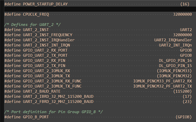
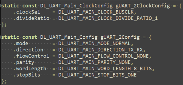
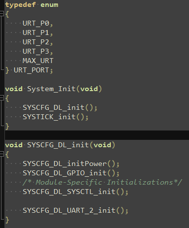
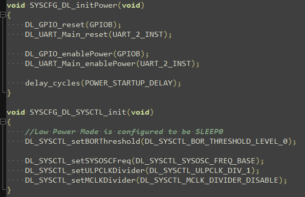
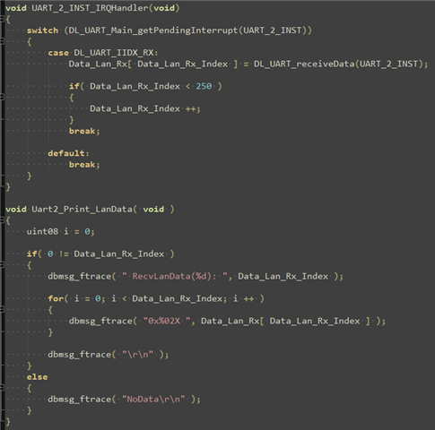
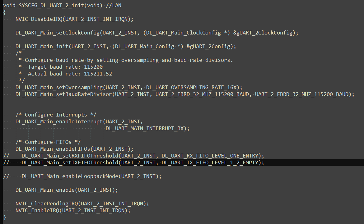
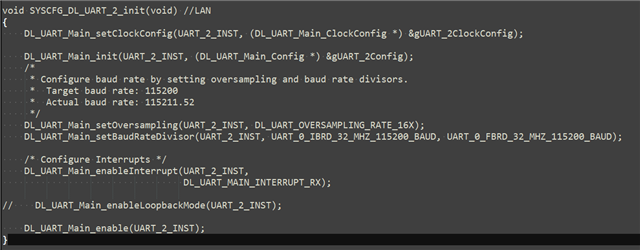
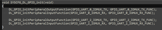
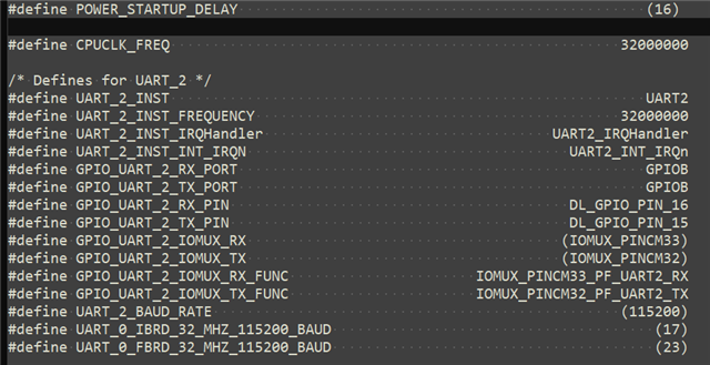
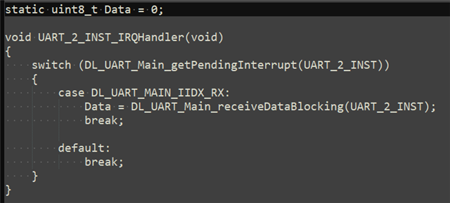
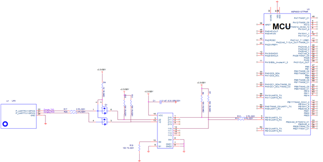
We used MSPM0G1107 PB16 pin as Uart2 RX, but we can't receive correct data. We always receive 0x00.

The code is created by CCS Tool, and we use a logic analyzer to confirm receipt of data(baud rate: 115200);
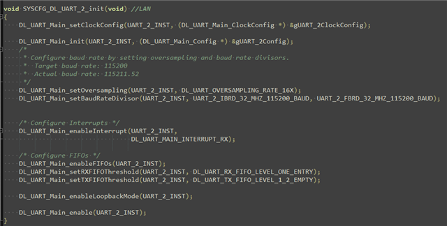
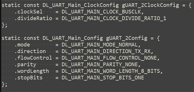
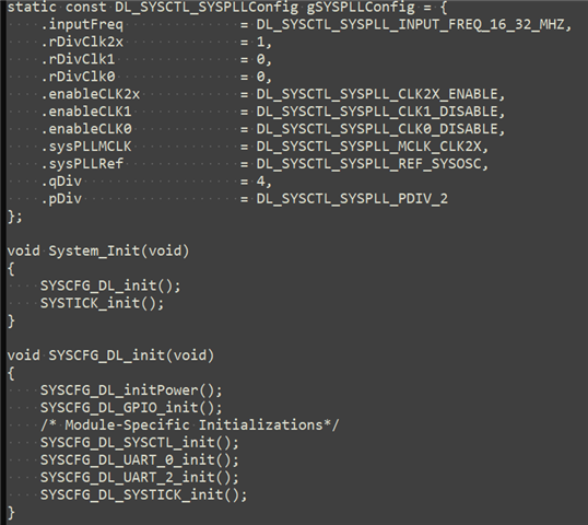
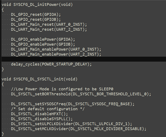
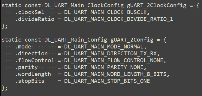
Below are our configuration. Please help confirm if there are any configuration errors in the configuration instructions.


  • Hi Afly,

    When loopback mode is enabled, the IO pins cannot be used to observe communication. The following is an excerpt from the TRM illustrating UART operation with loopback.

    Best Regards,
    Brian

  • We change SYSCFG_DL_UART_2_init function as below( remove loopback mode ), but we still can not receive correct data from UART_2_INST_IRQHandler.

    Below is the new code of SYSCFG_DL_UART_2_init:

  • Please create a new source code for Uart2 with 115200 bardrate based on our system clock configuration.

    Requirement: Uart2 interrupt can receive correct data.

  • HI Afly,

    I've modified the external loopback example for the LP-MSPM0G3507 to use the MSPM0G1107 image. I believe it meets your clock requirements; the baud rate is 115200, and I was able to update a variable with the received message within the interrupt handler. For set up, you will need to short the TX and RX pins, and you may need to reconfigure the pins used to fit your device configuration.

    uart_external_loopback_interrupt_MSPM0G1107_nortos_ticlang.zip

    Best Regards,
    Brian

  • We used the code you provided, short the TX and RX pins and print the data from RX, it's correct.

    But if we connect the MCU Uart2 RX port to another board's Uart TX port with baud rate 115200, we still can't receive correct data.

    We measured the waveform of MCU Uart2 RX by using an oscilloscope and confirmed that the data from another board's uart port is correct (voltage&Bard Rate=8.6us).


  • Hi Afly,

    Would you be able to share a pin diagram of the two devices? If you're able to send the correct data from one MCU and confirmed the external loopback on the other is working, this issue is likely from the hardware set up. Can you make sure the two boards are also sharing the same ground?

    Best Regards,
    Brian

  • We confirm that these two motherboards share the same ground.
    We are currently working on OTA functionality. The Uart2 is configured with a baud rate of 115200 in order for the MCU to receive data from the LANBoard, which is used to flash data to the MCU's App Flash section (we partition the MCU into BootLoader and App sections, and OTA is the process of updating the App section's data).
    We confirm that the App section can correctly receive data from LANBoard, but the BootLoader section can not implemente so.
    We tried to move all the configurations in the App section to the BootLoader section, but Uart2 still cannot receive LANBoard data correctly.

  • Hi Afly,

    I have a few questions regarding your bootloader:

    Are you using BSL or a custom bootloader?

    How are you entering your bootloader mode?

    Have you confirmed that your bootloader has been entered?

    There are BSL code examples using UART in the SDK, and documents going over operation and implementation. I will include links to the documents below.

    Best Regards,
    Brian

  • We didn't use BSL. We configured BootLoader and App partitions by configuring "mspm0g3507.sct".

    We confirm that we can enter the BootLoader partition normally because after entering the BootLoader partition, Uart0 will print the corresponding debug information.

    BTW, we also configured Uart0 as 115200 baudrate, which can correctly send and receive data through Uart0 interrupt.

    Below is ouw BootLoader and App partitions "mspm0g3507.sct":

  • Hi Afly,

    Our AE   has provided an example for UART2 communication, and another AE also tested with this example on launchpad with the same IO (PB15 & PB16) same as your schematic, and it works well.
    Have you tried to directly use the same example (just change the UART2 RX and TX pin) in your board and test for UART communication?
    And also, please check whether NVIC_EnableIRQ(UART_2_INST_INT_IRQN); API is applied in your lasted software.

  • Hi Afly,

    It looks like you're able to enter debug mode while running your bootloader. Can you check the uart2 configuration register values to make sure the configuration of your non-working code matches your working code?

    Can you also check the RIS register values periodically as you run your code? If you aren't able to catch the communication within an interrupt handler, the RIS registers will indicate whether there is one to be caught at all.

    Best Regards,
    Brian

  • The mainboard has been temporarily verified for other functions.
    Let me summarize the overall situation here first:
    1. The chip we used is MSPM0G1107
    2. The BootLoader and App partitions do use TI BSL sample code, and are only configured by the LD_SROM1 partition. Under specific conditions, it can jump from the BootLoader to the App or jump back from the App to the BootLoader
    3. Currently, the clock configuration of BootLoader and App partition is completely the same
    4. Uart2 115200 configuration in the App partition can communicate with LANBoard (both sending and receiving normally), while Uart2 115200 configuration in the BootLoader partition can not receice LANBoard data
    5. Shorting circuit Uart2's TX and RX in the BootLoader partition and configuring Uart2's baud rate to 115200, Uart2's RX can receive Uart2's TX data normally
    6. Uart0 115200 configuration in the BootLoader partition can send and receive data correctly
    7. The ports of BootLoader and App partition configuration Uart0 are PA10&PA11, and the ports configuration of Uart2 are PB15&PB16
    8. BootLoader partition Uart2 other baud rates configuration has not been verified yet(such as 9600)

  • This thread has become part of an email chain. I recommend we stick to email as the single medium for future correspondence.

    Best Regards,
    Brian