This thread has been locked.

If you have a related question, please click the "Ask a related question" button in the top right corner. The newly created question will be automatically linked to this question.

Problem on ADC sampling

Hi people,

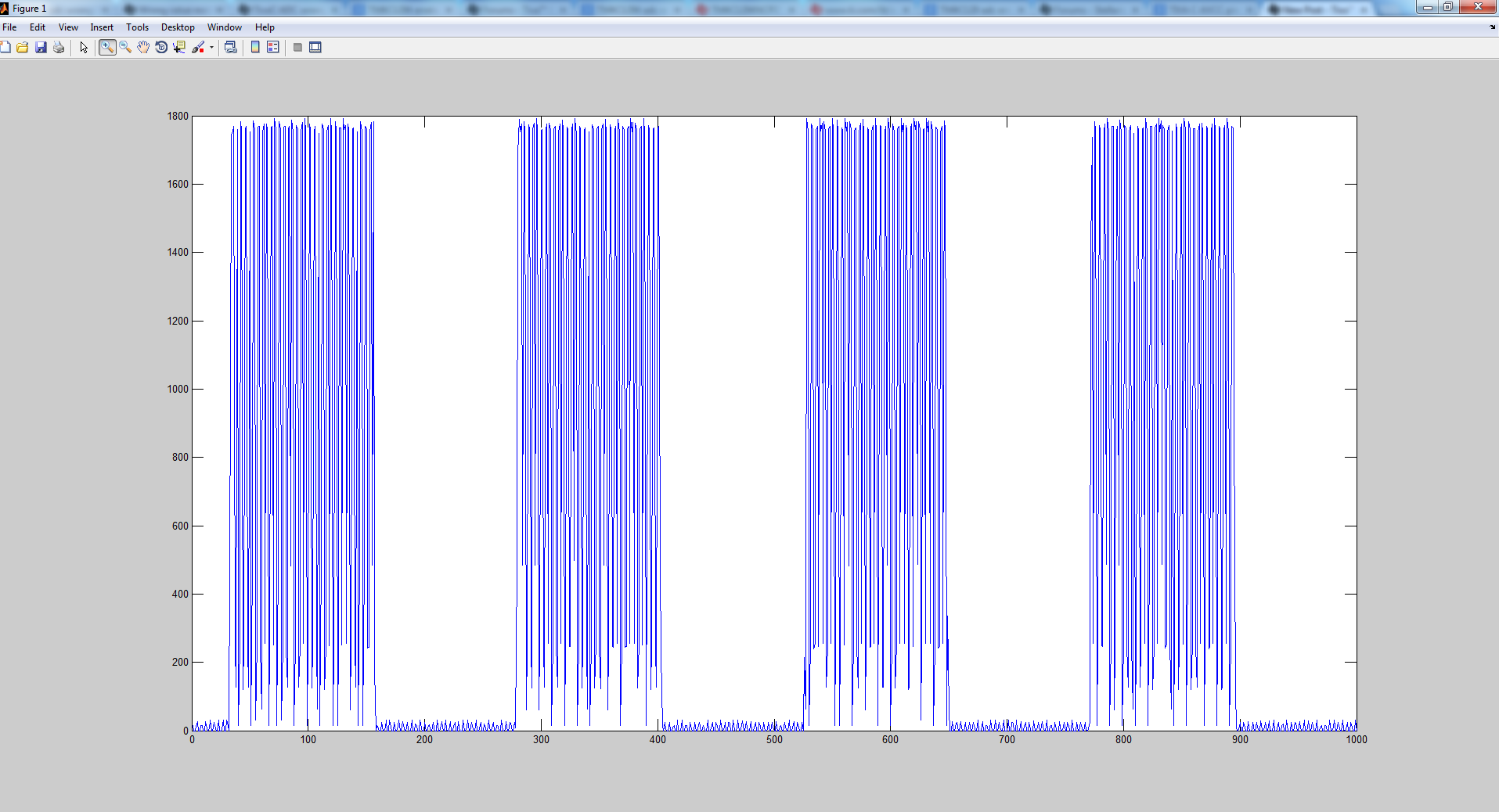
When digitalizing a 300 Hz square wave with a ADC triggered by a timer at 50 KHz, I don't get a pure square wave.. I have got a lot of glitches (several VCC to almost 0 transitions).

I am using a TIVA C TM4C1294XL evaluation kit.

The ADC is configured with a sequencer 3 and triggered by a 50000 Hz timer:

/**
* --------------------------------------------------------------------------
* Timer0
* --------------------------------------------------------------------------
*/
/* Configure the timer 0 as a 32-bit Timer in periodic mode. It combines timer 0A and
* Timer 0B (General Purpose Timer). TIMER0_BASE is the start of the timer registers for
* Timer0 in, the peripheral sectio nof the memory map.*/
TimerClockSourceSet(TIMER0_BASE, TIMER_CLOCK_SYSTEM);
TimerConfigure(TIMER0_BASE, TIMER_CFG_PERIODIC);
/*This function controls the ADC trigger output for the specified timer.
* If the bEnable parameter is true, then the timer’s ADC output trigger is enabled;
* otherwise it is disabled.*/
TimerControlTrigger(TIMER0_BASE, TIMER_A, true);
// Maintain this disabled!

TimerLoadSet(TIMER0_BASE, TIMER_A, (ui32SysClkFreq / (ap.ac_signal_frequency)) / 2 - 1);

TimerDisable(TIMER0_BASE, TIMER_A);
// Middle priority
IntPrioritySet(INT_TIMER0A, 1);

The ADC initialization code after the clocks and gpios configuration is: 

/**
* --------------------------------------------------------------------------
* ADC
* --------------------------------------------------------------------------
*/
/* ADC 0 - Disable */
ADCSequenceDisable(ADC0_BASE, 3);
/* ADC 1 - Disable */
//ADCSequenceDisable(ADC1_BASE, 3);

/* ADC0 - Sample Sequencer 1 - Timer Trigger the Sampling and Highest Priority*/
ADCSequenceConfigure(ADC0_BASE, 3, ADC_TRIGGER_TIMER, 0);
/* ADC1 - Sample Sequencer 1 - Timer Trigger the Sampling and Highest Priority*/
//ADCSequenceConfigure(ADC1_BASE, 3, ADC_TRIGGER_TIMER, 0);

/* ADC 0 - ADC_CTL_TS is the channel linked to the CH1*/
ADCSequenceStepConfigure(ADC0_BASE, 3, 0, ADC_CTL_CH1 | ADC_CTL_SHOLD_4 |ADC_CTL_IE |ADC_CTL_END);

/* ADC 1 - ADC_CTL_TS is the channel linked to the CH1*/
//ADCSequenceStepConfigure(ADC1_BASE, 3, 0, ADC_CTL_CH2 |ADC_CTL_IE |ADC_CTL_END);

/* ADC 0 - Enable the ADC sequencer 1.*/
ADCSequenceEnable(ADC0_BASE, 3);
/* ADC 1 - Enable the ADC sequencer 1.*/
//ADCSequenceEnable(ADC1_BASE, 3);

/* ADC 0 - Enables the specific vector associated with ADC0_BASE.*/
IntEnable(INT_ADC0SS3);
/* ADC 1 - Enables the specific vector associated with ADC1_BASE.*/
//IntEnable(INT_ADC1SS3);

/* ADC 0 - Enables a specific event*/
ADCIntEnable(ADC0_BASE, 3);
/* ADC 1 - Enables a specific event*/
//ADCIntEnable(ADC1_BASE, 3);

The ADC ISR code is:

/**
* \brief This function utilizes the ADC ISR to acquire samples from the ADC.
* @param void :
* @return void :
*/
void ADC0IntHandler(void)
{
uint32_t ui32ADC0Value;

/* ADC 0 - Clear the INterrupt Flag*/
ADCIntClear(ADC0_BASE, 3);

/* Disable Timer */
TimerDisable(TIMER0_BASE, TIMER_A);

/* ADC 0 - Get the data */
ADCSequenceDataGet(ADC0_BASE, 3, &ui32ADC0Value);

/* ADC 0 - Un-pend an interrupt */
IntPendClear(INT_ADC0SS3);

ram_store_b1[sf.nsamples_bridge1] = ui32ADC0Value;

sf.nsamples_bridge1++;

if(sf.nsamples_bridge1 >= ap.maximum_nsamples ) //&& sf.nsamples_bridge2 >= ap.maximum_nsamples)
{

sf.machine_state = MEASURE_COMPLETE_STATE;

}
else
{
/* Enable the timer */
//TimerLoadSet(TIMER0_BASE, TIMER_A, (ui32SysClkFreq / (ap.ac_signal_frequency)) / 2 - 1);
TimerEnable(TIMER0_BASE, TIMER_A);
}
}

Thank you.

  • Hello Daniel,

    Since this is not a complete code post, so let me put some points from a programming perspective

    1. Since the timer is a periodic mode timer, you do not need to disable and enable the same for every sample acquisition. Only when 50K samples from ADC are done, must you disable it. I would strongly ask to resolve this. In case you still need to do it this way, then suggest using ONE SHOT Mode

    2. IntPendClear need to be done as the clearing of the source of interrupt is sufficient.

    3. Instead of storing it in a buffer, can you print it on UART Terminal? And share the data.

    Regards

    Amit

  • Daniel Dinis said:
    ADC triggered by a timer at 50 KHz

    My read is that the ADC is triggered @ 50KHz - not that 50K ADC samples have been collected...

    At that rate - samples are collected @ 20uS intervals.   Dumping this data - via any serial port - is unlikely to keep up with this data rate - is it not?

    It's annoying for posters to burden their code w/extensive "commented out" lines/regions - demoralizes & slows the reviewer's task.   (and is not especially considerate/thoughtful - i.e. client values their time/comfort beyond that of their unpaid/hapless helpers! )  (even the paid helpers (Amit) should be treated w/care/consideration)

    I'd prefer to see the actual sampled data collection (raw) rather than the "hidden source" graph - we're asked to "trust" that all graphing ran successfully/smoothly - while the main ADC process did not...   (seems bit of a stretch...)

    In such troubleshooting - KISS always rules/runs our attempts.  If 50KHz fails (as it clearly does here) is it not useful to run at a far slower rate?  (say 5KHz?)  As success reveals - only then - "bump up the conversion rate" - until the system again, "runs amuck." 

    Note too that engineering coursework reveals certain theorems which define an adequate conversion rate based upon the highest frequency of interest to be captured.  50KHz is far beyond normal/customary for a 300Hz input signal...

    While a square wave has value - our group always tests w/a linear, ramping voltage signal.  This quickly/easily telegraphs what the next value in the conversion sequence should be.  Square wave shifts between 2 key values - far less revealing/helpful/insightful - than the suggested, linear ramping method...

  • Hi again,

    I found the bug , it was on the PC-side , everything is working now.

    Regards

  • Hello Daniel,

    Could you elaborate what the bug was so that community may benefit from it.

    Regards

    Amit

  • Amit Ashara said:
    Could you elaborate what the bug was so that community may benefit from it.

    @ Amit,

    Bless you for enforcing that discipline!  Such response is the analog of, "Does not Work!" (i.e. "It Works!") 

    If we read a 300Hz square wave (T = 3.33mS) @ 50K ADC rate (T = 20uS) - 83 samples should register high, 83 low.  (i.e. 3.33mS / 20uS = 166 ADC captures - if that can be achieved over one sample signal period)

    That sample rate seems tad more than Nyquist/others had suggested.

  • cb1_mobile said:
    That sample rate seems tad more than Nyquist/others had suggested.

     I suppose manyfold Shannon prone than Nyquist... This guy was saving to ram but no info how and when it was transferring data, if you transfer at 115KBaud you get a similar sample error and mangling too, see also the ground floor noise and same frequency is there.. do a simple (at eye) fft and voila' 50/115 rate is visible without math too ;)

     I am learning read from Magic sphere, Amit are you betting on? ;)

  • Hello again,

    Excuse me since it was the first time that I'm posting something on a forum.

    The firmware is working good.. It acquires X samples, stores them in RAM, and at the end sends it to the PC. To reduce the overhead, sends everything in NON-ASCII (thus, 1 sample = 2 bytes)..

    The problem was due to the matlab function dec2bin which when concatenating the two nibbles, omitted the 0's on the left of the least significant nibble, decreasing the value.

    Thanks again