This thread has been locked.

If you have a related question, please click the "Ask a related question" button in the top right corner. The newly created question will be automatically linked to this question.

On which port does the switches are located on my lauchpad?

Other Parts Discussed in Thread: TM4C123GH6PM, EK-TM4C123GXL

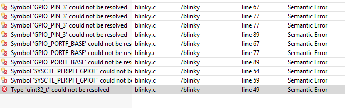
I am using TM4C123Gh6PM, trying to figure out where to look for switches on datasheet. How to configure those two switches located on my launchpad? Do you have any tutorials and examples on it? 

  • Hello Gaurav

    Did you check the schematics for the EK-TM4C123GXL in the User Guide?

    Regards
    Amit
  • I saw it is connected to USR_SW1. I am facing an error after using this.
  • Hello Gaurav

    And what is the error?

    Regards
    Amit
  • It didn't like SYSCTDELAY(2000000); // wait function
    I think so that i haven't declared.
  • Hello Gaurav,

    No code, no post coherency, no clear issue description. How are we supposed to debug and resolve your issue?

    Regards
    Amit
  • #include <stdint.h>
    #include "inc/tm4c123gh6pm.h"
    #define USR_SW1 0X0001

    //*****************************************************************************
    //
    //! \addtogroup example_list
    //! <h1>Blinky (blinky)</h1>
    //!
    //! A very simple example that blinks the on-board LED using direct register
    //! access.
    //
    //*****************************************************************************

    //*****************************************************************************
    //
    // Blink the on-board LED.
    //
    //*****************************************************************************
    int main(void)
    {
    volatile uint32_t ui32Loop;

    //
    // Enable the GPIO port that is used for the on-board LED.
    //
    SYSCTL_RCGC2_R = SYSCTL_RCGC2_GPIOF;

    //
    // Do a dummy read to insert a few cycles after enabling the peripheral.
    //
    ui32Loop = SYSCTL_RCGC2_R;

    //
    // Enable the GPIO pin for the LED (PF3). Set the direction as output, and

    //
    GPIO_PORTF_DIR_R = 0x08;
    GPIO_PORTF_DEN_R = 0x08; // enable the GPIO pin for digital function.

    //
    // Loop forever.
    //
    while(1)
    {
    if(USR_SW1==0)
    {
    GPIO_PORTF_DATA_R |= 0x08;
    SYSCTLDELAY(200000);
    GPIO_PORTF_DATA_R &= ~(0x08);

    }
    }
    }
  • Hello Gaurav,

    I would not recommend using DRM style of coding as the chances of making mistakes and readability of the code (with your project growing) increases beyond comprehension. Please use TivaWare.

    Now coming to coding basics...

    #define USR_SW1 0X0001

    and later

    if(USR_SW1==0)

    which will evaluate as

    if(0x0001==0) and that is never true.

    You need to configure the GPIO corresponding to the switch as an input, enable the IO pull up and then read the Pin State and compare it against 1 or 0 to detect a switch. The schematic clearly shows that there is no pull up on the path, so the switch shall always read as 0. Only be enabling a pull up in the IO, will a switch press be detected as 0 and a switch release as 1.

    Regards
    Amit
  • Hi Amit 

    I am not using DRM style now. 

    //*****************************************************************************
    //
    // blinky.c - Simple example to blink the on-board LED.
    //
    // Copyright (c) 2012-2015 Texas Instruments Incorporated. All rights reserved.
    // Software License Agreement
    //
    // Texas Instruments (TI) is supplying this software for use solely and
    // exclusively on TI's microcontroller products. The software is owned by
    // TI and/or its suppliers, and is protected under applicable copyright
    // laws. You may not combine this software with "viral" open-source
    // software in order to form a larger program.
    //
    // THIS SOFTWARE IS PROVIDED "AS IS" AND WITH ALL FAULTS.
    // NO WARRANTIES, WHETHER EXPRESS, IMPLIED OR STATUTORY, INCLUDING, BUT
    // NOT LIMITED TO, IMPLIED WARRANTIES OF MERCHANTABILITY AND FITNESS FOR
    // A PARTICULAR PURPOSE APPLY TO THIS SOFTWARE. TI SHALL NOT, UNDER ANY
    // CIRCUMSTANCES, BE LIABLE FOR SPECIAL, INCIDENTAL, OR CONSEQUENTIAL
    // DAMAGES, FOR ANY REASON WHATSOEVER.
    //
    // This is part of revision 2.1.2.111 of the EK-TM4C123GXL Firmware Package.
    //
    //*****************************************************************************

    #include <stdint.h>
    #include <stdbool.h>
    #include "inc/hw_memmap.h"
    #include "driverlib/gpio.h"
    #include "driverlib/sysctl.h"

    //*****************************************************************************
    //
    //! \addtogroup example_list
    //! <h1>Blinky (blinky)</h1>
    //!
    //! A very simple example that blinks the on-board LED using direct register
    //! access.
    //
    //*****************************************************************************

    //*****************************************************************************
    //
    // Blink the on-board LED.
    //
    //*****************************************************************************
    int
    main(void)
    {
    volatile uint32_t ui32Loop;

    //
    // Enable the GPIO port that is used for the on-board LED.
    //
    SysCtlPeripheralEnable(SYSCTL_PERIPH_GPIOF);

    //
    // Check if the peripheral access is enabled.
    //
    while(!SysCtlPeripheralReady(SYSCTL_PERIPH_GPIOF))
    {
    }

    //
    // Enable the GPIO pin for the LED (PF3). Set the direction as output, and
    // enable the GPIO pin for digital function.
    //
    GPIOPinTypeGPIOOutput(GPIO_PORTF_BASE, GPIO_PIN_3);

    //
    // Loop forever.
    //
    while(1)
    {
    //
    // Turn on the LED.
    //
    GPIOPinWrite(GPIO_PORTF_BASE, GPIO_PIN_3, GPIO_PIN_3);

    //
    // Delay for a bit.
    //
    for(ui32Loop = 0; ui32Loop < 200000; ui32Loop++)
    {
    }

    //
    // Turn off the LED.
    //
    GPIOPinWrite(GPIO_PORTF_BASE, GPIO_PIN_3, 0x0);

    //
    // Delay for a bit.
    //
    for(ui32Loop = 0; ui32Loop < 200000; ui32Loop++)
    {
    }
    }
    }

  • Hello Gaurav

    You need to include the file "inc/hw_types.h"

    Also please make sure that the include file path is defined.

    Regards
    Amit