This thread has been locked.

If you have a related question, please click the "Ask a related question" button in the top right corner. The newly created question will be automatically linked to this question.

TM4C129 and USB3300

Other Parts Discussed in Thread: EK-TM4C129EXL

Hello, I have a USB3300 board www.waveshare.com/usb3300-usb-hs-board.htm , I want to use it to achieve HS USB, I have configurated the pins and the main activity like this:

void USBULPIPinoutSet(void)
{
	//
	// Enable all the peripherals that are used by the ULPI interface.
	//
	ROM_SysCtlPeripheralEnable(SYSCTL_PERIPH_GPIOB);
	ROM_SysCtlPeripheralEnable(SYSCTL_PERIPH_GPIOL);
	ROM_SysCtlPeripheralEnable(SYSCTL_PERIPH_GPIOM);
	ROM_SysCtlPeripheralEnable(SYSCTL_PERIPH_GPIOP);
	ROM_SysCtlPeripheralEnable(SYSCTL_PERIPH_USB0);
	//
	// ULPI Port B pins.
	//
	ROM_GPIOPinConfigure(GPIO_PB2_USB0STP);
	ROM_GPIOPinConfigure(GPIO_PB3_USB0CLK);
	ROM_GPIOPinTypeUSBDigital(GPIO_PORTB_BASE, GPIO_PIN_2 | GPIO_PIN_3);
	GPIOPadConfigSet(GPIO_PORTB_BASE, GPIO_PIN_2 | GPIO_PIN_3, GPIO_STRENGTH_12MA, GPIO_PIN_TYPE_STD);
	//
	// ULPI Port P pins.
	//
	ROM_GPIOPinConfigure(GPIO_PP2_USB0NXT);
	ROM_GPIOPinConfigure(GPIO_PP3_USB0DIR);
	ROM_GPIOPinConfigure(GPIO_PP4_USB0D7);
	ROM_GPIOPinConfigure(GPIO_PP5_USB0D6);
	ROM_GPIOPinTypeUSBDigital(GPIO_PORTP_BASE, GPIO_PIN_2 | GPIO_PIN_3 | GPIO_PIN_4 | GPIO_PIN_5);
	GPIOPadConfigSet(GPIO_PORTP_BASE, GPIO_PIN_2 | GPIO_PIN_3 | GPIO_PIN_4 | GPIO_PIN_5, GPIO_STRENGTH_12MA, GPIO_PIN_TYPE_STD);
	//
	// ULPI Port L pins.
	//
	ROM_GPIOPinConfigure(GPIO_PL5_USB0D5);
	ROM_GPIOPinConfigure(GPIO_PL4_USB0D4);
	ROM_GPIOPinConfigure(GPIO_PL3_USB0D3);
	ROM_GPIOPinConfigure(GPIO_PL2_USB0D2);
	ROM_GPIOPinConfigure(GPIO_PL1_USB0D1);
	ROM_GPIOPinConfigure(GPIO_PL0_USB0D0);
	ROM_GPIOPinTypeUSBDigital(GPIO_PORTL_BASE, GPIO_PIN_0 | GPIO_PIN_1 | GPIO_PIN_2 | GPIO_PIN_3 | GPIO_PIN_4 | GPIO_PIN_5);
	GPIOPadConfigSet(GPIO_PORTL_BASE , GPIO_PIN_0 | GPIO_PIN_1 | GPIO_PIN_2 | GPIO_PIN_3 | GPIO_PIN_4 | GPIO_PIN_5, GPIO_STRENGTH_12MA, GPIO_PIN_TYPE_STD);
	//
	// ULPI Port M pins used to control the external USB oscillator and the
	// external USB phy on the DK-TM4C129X-DPHY board.
	//
	// PM1 - Enables the USB oscillator on the DK-TM4C129X-DPHY board.
	// PM3 - Enables the USB phy on the DK-TM4C129X-DPHY board.
	//
	ROM_GPIOPinTypeGPIOOutput(GPIO_PORTM_BASE, GPIO_PIN_1 | GPIO_PIN_3);
	ROM_GPIOPinWrite(GPIO_PORTM_BASE, GPIO_PIN_1 | GPIO_PIN_3, GPIO_PIN_1 | GPIO_PIN_3);

	USBClockEnable(USB0_BASE,1,USB_CLOCK_EXTERNAL);
	USBULPIEnable(USB0_BASE);												// Enable ULPI
	USBULPIConfig(USB0_BASE, USB_ULPI_EXTVBUS | USB_ULPI_EXTVBUS_IND);		// Configure the ULPI
	USBHighSpeed(USB0_BASE, true);											// Enable High Speed

}

int main(void)
{
    uint32_t ui32SysClock;
    uint32_t ui32PLLRate;
//  uint32_t ui32Setting;

    ui32SysClock = MAP_SysCtlClockFreqSet((SYSCTL_XTAL_25MHZ |
                                           SYSCTL_OSC_MAIN |
                                           SYSCTL_USE_PLL |
                                           SYSCTL_CFG_VCO_480), 120000000);

    PinoutSet(false, true);
    g_bUSBConfigured = false;

    ROM_SysTickPeriodSet(ui32SysClock / SYSTICKS_PER_SECOND);
    ROM_SysTickIntEnable();
    ROM_SysTickEnable();
    USBULPIPinoutSet();
    USBBufferInit(&g_sTxBuffer);
    USBBufferInit(&g_sRxBuffer);


    //SysCtlVCOGet(SYSCTL_XTAL_25MHZ, &ui32PLLRate);
    ui32PLLRate = 0;
    USBDCDFeatureSet(0, USBLIB_FEATURE_CPUCLK, &ui32SysClock);
    USBDCDFeatureSet(0, USBLIB_FEATURE_USBPLL, &ui32PLLRate);

    uint32_t ui32ULPI = USBLIB_FEATURE_ULPI_HS;
    USBDCDFeatureSet(0, USBLIB_FEATURE_USBULPI, &ui32ULPI);

    USBStackModeSet(0, eUSBModeForceDevice, 0);
    USBDBulkInit(0, &g_sBulkDevice);

    while(1)
    {
    }
}

This was made using the usb_dev_bulk example, the problem is that the Host (my PC) does not recognize the device, Is there any problem with the configuration?, some changes must be done on the host side??. Without the external ULPI PHY , everything works fine, the host recognize the device and the Visual Studio example proyect works fine. Someone has worked with this USB3300 board that I have used???

  • Hello Josue,

    Which TivaWare version are you using and how are you controlling the power down and reset of the USB3300?
  • TivaWare_C_Series-2.1.3.156, power down???? reset???!!!!, I have just connected 3.3V and GND to the voltage source and GND of the Launchpad, the reset pin of the USB3300 board is not connected to anything and I have not configured a reset controller on the code.....
    I have just connected and configure (I hope it's ok) Data pins from 0 to 7, STP, NXT, DIR and CLK.

    I have used the ULPI configuration from this post, the one that Paul propose:

    https://e2e.ti.com/support/microcontrollers/tiva_arm/f/908/t/322331

  • Hello Josue,

    If you check the TivaWare 2.1.3.156 there is an additional configuration of SysCtlVCOGet API call that has been added. This is must for the correct configuration of the USB MAC controller.

    I am not sure how the USB3300 board (from waveshare) will respond with floating Power Down and Reset on the USB3300.. In my setup I connected them to GPIO's so that the pins are under software control from the TM4C
  • Did you mean: SysCtlVCOGet(SYSCTL_XTAL_25MHZ, &ui32PLLRate); ??? (this line was not on TivaWare_C_Series-2.1.2.111)
    How does the power and de reset have to be controlled?? when they have to be set up and down?? Did you used any other USB3300 board???

  • Hello Josue

    This was a change made from TivaWare 2.1.2.111 to 2.1.3.156 (please see the release notes).

    I have my own board where USB3300 and TM4C are on the same PCB (this is an upcoming TI Design). I have mapped the PWDN and RESET to spare GPIO of TM4C and then based on the USB3300 recommendation, I drive the signals before commencing ULPI communication.
  • I see, did you see any error with the configuration?? besides the SysCtlVCOGet. I would like to know if it is OK. How about

        USBClockEnable(USB0_BASE,1,USB_CLOCK_EXTERNAL);
        USBULPIEnable(USB0_BASE);                                               // Enable ULPI
        USBULPIConfig(USB0_BASE, USB_ULPI_EXTVBUS | USB_ULPI_EXTVBUS_IND);      // Configure the ULPI
        USBHighSpeed(USB0_BASE, true);                                          // Enable High Speed

    This line are in the correct place???

  • Hello Josue,

    After intializing the IO, I release the Reset and Power Down to the USB3300. Once that is done, the next steps for my code is

    //
    // Enable the use of an external USB ULPI connected PHY or internal PHY
    // based on USB mode selection
    //
    SysCtlVCOGet(SYSCTL_XTAL_25MHZ, &ui32PLLRate);
    USBDCDFeatureSet(0, USBLIB_FEATURE_CPUCLK, &ui32SysClock);
    USBDCDFeatureSet(0, USBLIB_FEATURE_USBPLL, &ui32PLLRate);

    ui32ULPI = USBLIB_FEATURE_ULPI_HS;
    USBDCDFeatureSet(0, USBLIB_FEATURE_USBULPI, &ui32ULPI);

    //
    // Initialize the USB stack for device mode.
    //
    USBStackModeSet(0, eUSBModeForceDevice, 0);

    //
    // Pass our device information to the USB library and place the device
    // on the bus.
    //
    USBDBulkInit(0, &g_sBulkDevice);
  • How do you drive the signals from the TM4C (Link) to the PHY??, What do you mean saying " I release the Reset and Power Down to the USB3300." power down??, I realize with an osciloscope than the USB3300 chip is not generating the 60MHz CLK, the one that is generating the CLK output is the MCU, I thougth that the MCU with the line:

    	USBClockEnable(USB0_BASE,1,USB_CLOCK_EXTERNAL);
    

    Was going to receive the CLK signal for the USB from the USB3300 chip.

  • Hello Josue,

    This is managed by the USBLibrary and based on what the USB3300 supports. Input or Output clock mode.
  • Ok it is possible to configure the MCU to receive the clock signal, but how the USB3300 generate the clk?? something have to be sended from the MCU to the PHY to generate the CLK from it?
  • Hello Josue,

    I do not trust the waveshare product information (seen more issues that have taken almost a week to debug). Check the USB3300 datasheet. If it states that the ULPI clock is an input to the USB3300 device as default, then check USBCC register to see if it is correctly configured.
  • Reading more about the USB3300, I have found that there are registers that must be modified, for example the default value of the register that configures the speed is configurated to work only at FS, not HS, if I am correct (I hope) this registers must be modified with the USBULPIRegWrite command, also the USBULPIRegRead command shows the value of the register that is configurated on the USB3300. I have one question.... When does it come out the TI design for the USB3300???
  • Hello Josue,

    It will take 3-4 weeks for the Design Guide, Software and the Board files to come out.
  • Hello Amit.
    I have a doubt, the USB3300 data sheet says that the USB3300 can not use an external CLK source, it must be generated by the USB3300 to the link or controller (TM4C), what are the steps to make it generate the 60MHz clk signal??
  • Hello Josue

    Yes. USB3300 data sheet has the following information on the CLKOUT pin.

    14 CLKOUT Output, CMOS N/A 60MHz reference clock output. All ULPI signals are driven synchronous to the rising edge of this clock.

    So basically the configuration information given earlier should be good to use as I have USB3300 working with my custom board. If the USB3300 is not generating this clock then you would need to see if the 3.3V and 1.8V is proper on the USB3300 device, the crystal is correctly oscillating, Reset is High.
  • Hello Amit
    I have another question, in your design VDD1.8 adn VDDA1.8, are connected to a 1.8 voltage source?? or are connected to cappacitor and then ground???
  • Hello Josue

    It is connected to Cap and then GND. This function is controlled by the REG_EN pin. It must be connected to 3.3V
  • 5V is necesary for the USB connection (VBUS)??, I am comfused about 5V and 3.3 V, what is 5V source for? the 5V voltage source from the TM4C launchpad must be use here?.
    Thanks

  • Hello Josue

    Now you are confusing me. Earlier you are speaking about 1.8V and now you have changed tracks to 5V.

    Can you first check if the power supply and reset to the USB3300 is in correct state and the USB crystal attached to the USB3300 is oscillating
  • Ok, this this the configuration for voltage supply and reset:

    	ROM_GPIOPinTypeGPIOOutput(GPIO_PORTK_BASE, GPIO_PIN_1 | GPIO_PIN_2);
    	ROM_GPIOPinWrite(GPIO_PORTK_BASE,GPIO_PIN_1,GPIO_PIN_1);				//3.3V
    	ROM_GPIOPinWrite(GPIO_PORTK_BASE,GPIO_PIN_2,0x0);						//Reset off
    	DelayF(100);
    	ROM_GPIOPinWrite(GPIO_PORTK_BASE,GPIO_PIN_2,GPIO_PIN_2);				//Reset on

    I dont really know the way to test an on board crystal...

    I did this:

    I have connected an osciloscope to one pin of the crystal an GND, then I test with the other pin of the crystal and GND, I am just receiving voltage levels, I am not watching any sine wave on the osciloscope. This is the proper way to test an on board crystal?

  • Hello Josue

    Check the Amplitude and Time resolution of the scope. You should see a good sine waveform. If not then the issue is with the crystal connected to the USB3300. For sanity check you can do the same with the TM4C129x crystal as well.
  • the osciloscope must be connected to both pins of the crystal??? or one to GND??
  • Hello Josue,

    Ground of the oscillator to Ground of the board. The probe then touches the crystal lead.
  • Hi Amit, The probes from the oscilloscope I am using are not high impedance differential probes, the common probes that I am using stop  the oscilator and I can not see the sine wave,I have to test the oscilator separately from the board. I will change the oscilator from one of my two usb3300 boards.

  • Hello Josue

    I think that is your call. A normal passive probe should not cause that (I have used Passive probes from Agilent and Tek for scoping crystal and never seen to have a problem)
  • Hello Amit, using the FFT function of the oscilloscope I was able to watch the 24MHz oscillation peak, this only happens in a small time after connecting the probe to the crystal head, but it was visible, so... the crystal oscilators from my 2 USB3300 boards are working, but there is no CLK output from the chip. Before I knew that the USB3300 is not able to receive the CLK  from the MCU, I connect the 60MHz clk out from the MCU (that generates a 60 MHZ sine wave mounted over 1.8V) to the CLKOUT from the USB3300, do you think that putting a signal on an output pin of the USB3300 can ruined it??(CLK pin only works as an output)


  • Hello Josue,

    I would NOT do that. We are not sure why CLKOUT from the USB3300 is not being generated and adding the code to output the clock from MCU may cause mutliple drivers.

    What is this 60MHz sine wave mounted over 1.8V?
  • Hi Amit

    After some time desinging other part of my project I connect the ULPI board to an independent 3.3 voltage source, with this the ULPI board generates de 60 MHz clk signal from the CLKOUT pin with no problem, so I have made a modificaition to the code:

    ROM_GPIOPinTypeGPIOOutput(GPIO_PORTK_BASE, GPIO_PIN_1 | GPIO_PIN_2);
    GPIOPadConfigSet(GPIO_PORTK_BASE , GPIO_PIN_1 | GPIO_PIN_2 , GPIO_STRENGTH_12MA, GPIO_PIN_TYPE_STD);
    ROM_GPIOPinWrite(GPIO_PORTK_BASE,GPIO_PIN_1,GPIO_PIN_1); //3.3V
    ROM_GPIOPinWrite(GPIO_PORTK_BASE,GPIO_PIN_2,0x0); //Reset off
    DelayF(100);
    ROM_GPIOPinWrite(GPIO_PORTK_BASE,GPIO_PIN_2,GPIO_PIN_2); //Reset on

    Whit this I thougth that the USB3300 will have enough power to work, but this happend (The images are from the CLKOUT pin of the USB3300):

    Mostrando IMG-20161119-WA0010.jpg

     Zoom to the one of those peaks:

    Mostrando IMG-20161119-WA0009.jpg

    Mostrando IMG-20161119-WA0008.jpg

    The USB3300 is generating the 60 MHZ CLK signal for short times, this mean that the 3.3V source (GPIO K1) from the lauchpad is not giving enough power (current) to the ULPI module, What would you recommend me?? changing the voltage source for the launch pad (not using the USB as a voltage source) would be the better option??

  • Hello Josue,

    If that would have been the case, the chances are that TM4C would also be going through resets. If the LDO is getting overloaded, then check the 3.3V voltage rail. If you see significant dips then that could be the case.

    As a side note the USBHS reference design is expected to be out by next week.
  • Hi Amit

    Now the Voltage source is not a problem, it is solved, I have configured the MCU to receive the 60 MHZ CLK that the USB3300 is generating, But I am not able to read the values of the USB3300 registers. the code gets stucks, so I assume that something is wrong with the configuration of the communication between the MCU and the USB3300. The code is a copy of the usb_dev_bulk example with the ULPI configuration:


    #include <stdbool.h>
    #include <string.h>
    #include <stdint.h>
    #include <stdio.h>
    #include <stdlib.h>
    #include "inc/hw_ints.h"
    #include "driverlib/interrupt.h"
    #include "driverlib/sysctl.h"
    //#include "driverlib/systick.h"
    #include "driverlib/rom.h"
    #include "inc/hw_memmap.h"
    #include "driverlib/gpio.h"
    #include "driverlib/rom_map.h"
    #include "usblib/usblib.h"
    #include "usblib/usb-ids.h"
    #include "usblib/device/usbdevice.h"
    #include "usblib/device/usbdbulk.h"
    #include "utils/uartstdio.h"
    #include "utils/ustdlib.h"
    #include "drivers/pinout.h"
    #include "usb_bulk_structs.h"
    
    #include "inc/hw_adc.h"
    #include "inc/hw_types.h"
    #include "inc/hw_udma.h"
    #include "inc/hw_emac.h"
    #include "driverlib/debug.h"
    #include "driverlib/timer.h"
    #include "driverlib/pin_map.h"
    #include "driverlib/rom.h"
    #include "driverlib/uart.h"
    #include "driverlib/adc.h"
    #include "driverlib/udma.h"
    #include "driverlib/emac.h"
    #include "driverlib/pwm.h"
    #include "driverlib/usb.h"
    
    #define SYSTICKS_PER_SECOND 100
    #define SYSTICK_PERIOD_MS   (1000 / SYSTICKS_PER_SECOND)
    
    volatile uint32_t g_ui32SysTickCount = 0;
    volatile uint32_t g_ui32TxCount = 0;
    volatile uint32_t g_ui32RxCount = 0;
    #define COMMAND_PACKET_RECEIVED 0x00000001
    #define COMMAND_STATUS_UPDATE   0x00000002
    
    uint32_t leFlagpapu = 1;
    uint8_t registro;
    volatile uint32_t g_ui32Flags = 0;
    static volatile bool g_bUSBConfigured = false;
    #ifdef DEBUG
    void
    __error__(char *pcFilename, uint32_t ui32Line)
    {
    }
    #endif
    
    void DelayF (uint32_t t)
    {
        volatile uint32_t ui32Loop;
        for(ui32Loop = 0; ui32Loop < t; ui32Loop++){}
    }
    
    void SysTickIntHandler(void)
    {
        g_ui32SysTickCount++;
    }
    
    static uint32_t EchoNewDataToHost(tUSBDBulkDevice *psDevice, uint8_t *pi8Data,
                      uint_fast32_t ui32NumBytes)
    {
        uint_fast32_t ui32Loop, ui32Space, ui32Count;
        uint_fast32_t ui32ReadIndex;
        uint_fast32_t ui32WriteIndex;
        tUSBRingBufObject sTxRing;
        USBBufferInfoGet(&g_sTxBuffer, &sTxRing);
        ui32Space = USBBufferSpaceAvailable(&g_sTxBuffer);
        ui32Loop = (ui32Space < ui32NumBytes) ? ui32Space : ui32NumBytes;
        ui32Count = ui32Loop;
        g_ui32RxCount += ui32NumBytes;
        ui32ReadIndex = (uint32_t)(pi8Data - g_pui8USBRxBuffer);
        ui32WriteIndex = sTxRing.ui32WriteIndex;
    
        while(ui32Loop)
        {
            if((g_pui8USBRxBuffer[ui32ReadIndex] >= 'a') &&
               (g_pui8USBRxBuffer[ui32ReadIndex] <= 'z'))
            {
                g_pui8USBTxBuffer[ui32WriteIndex] =
                    (g_pui8USBRxBuffer[ui32ReadIndex] - 'a') + 'A';
            }
            else
            {
                if((g_pui8USBRxBuffer[ui32ReadIndex] >= 'A') &&
                   (g_pui8USBRxBuffer[ui32ReadIndex] <= 'Z'))
                {
                    g_pui8USBTxBuffer[ui32WriteIndex] =
                        (g_pui8USBRxBuffer[ui32ReadIndex] - 'Z') + 'z';
                }
                else
                {
                    g_pui8USBTxBuffer[ui32WriteIndex] =
                        g_pui8USBRxBuffer[ui32ReadIndex];
                }
            }
    
            ui32WriteIndex++;
            ui32WriteIndex =
                (ui32WriteIndex == BULK_BUFFER_SIZE) ? 0 : ui32WriteIndex;
    
            ui32ReadIndex++;
    
            ui32ReadIndex = ((ui32ReadIndex == BULK_BUFFER_SIZE) ?
                             0 : ui32ReadIndex);
    
            ui32Loop--;
        }
    
        USBBufferDataWritten(&g_sTxBuffer, ui32Count);
        return(ui32Count);
    }
    uint32_t TxHandler(void *pvCBData, uint32_t ui32Event, uint32_t ui32MsgValue,
              void *pvMsgData)
    {
        if(ui32Event == USB_EVENT_TX_COMPLETE)
        {
            g_ui32TxCount += ui32MsgValue;
        }
        return(0);
    }
    
    uint32_t RxHandler(void *pvCBData, uint32_t ui32Event, uint32_t ui32MsgValue,void *pvMsgData)
    {
        switch(ui32Event)
        {
            case USB_EVENT_CONNECTED:
            {
                g_bUSBConfigured = true;
                g_ui32Flags |= COMMAND_STATUS_UPDATE;
                USBBufferFlush(&g_sTxBuffer);
                USBBufferFlush(&g_sRxBuffer);
    
                break;
            }
            case USB_EVENT_DISCONNECTED:
            {
                g_bUSBConfigured = false;
                g_ui32Flags |= COMMAND_STATUS_UPDATE;
                break;
            }
            case USB_EVENT_RX_AVAILABLE:
            {
                tUSBDBulkDevice *psDevice;
                psDevice = (tUSBDBulkDevice *)pvCBData;
                return(EchoNewDataToHost(psDevice, pvMsgData, ui32MsgValue));
            }
            case USB_EVENT_SUSPEND:
            case USB_EVENT_RESUME:
                break;
            default:
                break;
        }
    
        return(0);
    }
    
    void USBULPIPinoutSet(void)
    {
    	//
    	// Enable all the peripherals that are used by the ULPI interface.
    	//									// Enable High Speed
    
        ROM_SysCtlPeripheralEnable(SYSCTL_PERIPH_GPIOB);
    	ROM_SysCtlPeripheralEnable(SYSCTL_PERIPH_GPIOL);
    	ROM_SysCtlPeripheralEnable(SYSCTL_PERIPH_GPIOM);
    	ROM_SysCtlPeripheralEnable(SYSCTL_PERIPH_GPIOP);
    	ROM_SysCtlPeripheralEnable(SYSCTL_PERIPH_GPIOK);
    	ROM_SysCtlPeripheralEnable(SYSCTL_PERIPH_USB0);
    
    	//
    	// ULPI Port B pins.
    	//
    
    	ROM_GPIOPinConfigure(GPIO_PB2_USB0STP);
    	ROM_GPIOPinConfigure(GPIO_PB3_USB0CLK);
    	ROM_GPIOPinTypeUSBDigital(GPIO_PORTB_BASE, GPIO_PIN_2 | GPIO_PIN_3);
    	GPIOPadConfigSet(GPIO_PORTB_BASE, GPIO_PIN_2 | GPIO_PIN_3, GPIO_STRENGTH_12MA, GPIO_PIN_TYPE_STD);
    
    	//
    	// ULPI Port P pins.
    	//
    	ROM_GPIOPinConfigure(GPIO_PP2_USB0NXT);
    	ROM_GPIOPinConfigure(GPIO_PP3_USB0DIR);
    	ROM_GPIOPinConfigure(GPIO_PP4_USB0D7);
    	ROM_GPIOPinConfigure(GPIO_PP5_USB0D6);
    	ROM_GPIOPinTypeUSBDigital(GPIO_PORTP_BASE, GPIO_PIN_2 | GPIO_PIN_3 | GPIO_PIN_4 | GPIO_PIN_5);
    	GPIOPadConfigSet(GPIO_PORTP_BASE, GPIO_PIN_2 | GPIO_PIN_3 | GPIO_PIN_4 | GPIO_PIN_5, GPIO_STRENGTH_12MA, GPIO_PIN_TYPE_STD);
    	//
    	// ULPI Port L pins.
    	//
    	ROM_GPIOPinConfigure(GPIO_PL5_USB0D5);
    	ROM_GPIOPinConfigure(GPIO_PL4_USB0D4);
    	ROM_GPIOPinConfigure(GPIO_PL3_USB0D3);
    	ROM_GPIOPinConfigure(GPIO_PL2_USB0D2);
    	ROM_GPIOPinConfigure(GPIO_PL1_USB0D1);
    	ROM_GPIOPinConfigure(GPIO_PL0_USB0D0);
    	ROM_GPIOPinTypeUSBDigital(GPIO_PORTL_BASE, GPIO_PIN_0 | GPIO_PIN_1 | GPIO_PIN_2 | GPIO_PIN_3 | GPIO_PIN_4 | GPIO_PIN_5);
    	GPIOPadConfigSet(GPIO_PORTL_BASE , GPIO_PIN_0 | GPIO_PIN_1 | GPIO_PIN_2 | GPIO_PIN_3 | GPIO_PIN_4 | GPIO_PIN_5, GPIO_STRENGTH_12MA, GPIO_PIN_TYPE_STD);
    	//
    	// ULPI Port M pins used to control the external USB oscillator and the
    	// external USB phy on the DK-TM4C129X-DPHY board.
    	//
    	// PM1 - Enables the USB oscillator on the DK-TM4C129X-DPHY board.
    	// PM3 - Enables the USB phy on the DK-TM4C129X-DPHY board.
    	//
    	ROM_GPIOPinTypeGPIOOutput(GPIO_PORTM_BASE, GPIO_PIN_1 | GPIO_PIN_3);
    	ROM_GPIOPinWrite(GPIO_PORTM_BASE, GPIO_PIN_1 | GPIO_PIN_3, GPIO_PIN_1 | GPIO_PIN_3);
    
        //ROM_GPIOPinWrite(GPIO_PORTK_BASE,GPIO_PIN_2, 0x0);					//Reset off
    
    	USBClockEnable(USB0_BASE,1,USB_CLOCK_EXTERNAL);
    	USBULPIEnable(USB0_BASE);												// Enable ULPI
    	USBULPIConfig(USB0_BASE, USB_ULPI_EXTVBUS | USB_ULPI_EXTVBUS_IND);		// Configure the ULPI
    	USBHighSpeed(USB0_BASE, true);											// Enable High Speed
    	registro = USBULPIRegRead(USB0_BASE, 0x00);
    
    }
    
    int main(void)
    {
        uint32_t ui32SysClock;
        uint32_t ui32PLLRate;
        uint32_t ui32ULPI;
    //  uint32_t ui32Setting;
    
        ui32SysClock = MAP_SysCtlClockFreqSet((SYSCTL_XTAL_25MHZ |
                                               SYSCTL_OSC_MAIN |
                                               SYSCTL_USE_PLL |
                                               SYSCTL_CFG_VCO_480), 120000000);
    
        PinoutSet(false, true);
        g_bUSBConfigured = false;
    
        ROM_SysTickPeriodSet(ui32SysClock / SYSTICKS_PER_SECOND);
        ROM_SysTickIntEnable();
        ROM_SysTickEnable();
    
    	ROM_GPIOPinTypeGPIOOutput(GPIO_PORTK_BASE, GPIO_PIN_1 | GPIO_PIN_2);
    	GPIOPadConfigSet(GPIO_PORTK_BASE , GPIO_PIN_1 | GPIO_PIN_2, GPIO_STRENGTH_12MA, GPIO_PIN_TYPE_STD);
    	ROM_GPIOPinWrite(GPIO_PORTK_BASE,GPIO_PIN_1,GPIO_PIN_1);				//3.3V
    	ROM_GPIOPinWrite(GPIO_PORTK_BASE,GPIO_PIN_2,0x0);						//Reset off
    	DelayF(100);
    	ROM_GPIOPinWrite(GPIO_PORTK_BASE,GPIO_PIN_2,GPIO_PIN_2);				//Reset on
    
        USBULPIPinoutSet();
        USBBufferInit(&g_sTxBuffer);
        USBBufferInit(&g_sRxBuffer);
    
    
        SysCtlVCOGet(SYSCTL_XTAL_25MHZ, &ui32PLLRate);
    
        ui32PLLRate = 0;
    
        USBDCDFeatureSet(0, USBLIB_FEATURE_CPUCLK, &ui32SysClock);
        USBDCDFeatureSet(0, USBLIB_FEATURE_USBPLL, &ui32PLLRate);
    
        ui32ULPI = USBLIB_FEATURE_ULPI_HS;
        USBDCDFeatureSet(0, USBLIB_FEATURE_USBULPI, &ui32ULPI);
    
        //
        // Initialize the USB stack for device mode.
        //
        USBStackModeSet(0, eUSBModeForceDevice, 0);
    
        //
        // Pass our device information to the USB library and place the device
        // on the bus.
        //
    
        USBDBulkInit(0, &g_sBulkDevice);
    
        while(1)
        {
        }
    }
    

    I do not know what is wrong,Can you guide me on this?


  • The 3.3 voltage rail looks fine, What I am not able to do is to read USB3300 registers, I dont know if something is wrong with the USBHS configuration on the MCU, this is the code, can you guide me please?

    #include <stdbool.h>
    #include <string.h>
    #include <stdint.h>
    #include <stdio.h>
    #include <stdlib.h>
    #include "inc/hw_ints.h"
    #include "driverlib/interrupt.h"
    #include "driverlib/sysctl.h"
    //#include "driverlib/systick.h"
    #include "driverlib/rom.h"
    #include "inc/hw_memmap.h"
    #include "driverlib/gpio.h"
    #include "driverlib/rom_map.h"
    #include "usblib/usblib.h"
    #include "usblib/usb-ids.h"
    #include "usblib/device/usbdevice.h"
    #include "usblib/device/usbdbulk.h"
    #include "utils/uartstdio.h"
    #include "utils/ustdlib.h"
    #include "drivers/pinout.h"
    #include "usb_bulk_structs.h"
    
    #include "inc/hw_adc.h"
    #include "inc/hw_types.h"
    #include "inc/hw_udma.h"
    #include "inc/hw_emac.h"
    #include "driverlib/debug.h"
    #include "driverlib/timer.h"
    #include "driverlib/pin_map.h"
    #include "driverlib/rom.h"
    #include "driverlib/uart.h"
    #include "driverlib/adc.h"
    #include "driverlib/udma.h"
    #include "driverlib/emac.h"
    #include "driverlib/pwm.h"
    #include "driverlib/usb.h"
    
    #define SYSTICKS_PER_SECOND 100
    #define SYSTICK_PERIOD_MS   (1000 / SYSTICKS_PER_SECOND)
    
    volatile uint32_t g_ui32SysTickCount = 0;
    volatile uint32_t g_ui32TxCount = 0;
    volatile uint32_t g_ui32RxCount = 0;
    #define COMMAND_PACKET_RECEIVED 0x00000001
    #define COMMAND_STATUS_UPDATE   0x00000002
    
    uint32_t leFlagpapu = 1;
    uint8_t registro;
    volatile uint32_t g_ui32Flags = 0;
    static volatile bool g_bUSBConfigured = false;
    #ifdef DEBUG
    void
    __error__(char *pcFilename, uint32_t ui32Line)
    {
    }
    #endif
    
    void DelayF (uint32_t t)
    {
        volatile uint32_t ui32Loop;
        for(ui32Loop = 0; ui32Loop < t; ui32Loop++){}
    }
    
    void SysTickIntHandler(void)
    {
        g_ui32SysTickCount++;
    }
    
    static uint32_t EchoNewDataToHost(tUSBDBulkDevice *psDevice, uint8_t *pi8Data,
                      uint_fast32_t ui32NumBytes)
    {
        uint_fast32_t ui32Loop, ui32Space, ui32Count;
        uint_fast32_t ui32ReadIndex;
        uint_fast32_t ui32WriteIndex;
        tUSBRingBufObject sTxRing;
        USBBufferInfoGet(&g_sTxBuffer, &sTxRing);
        ui32Space = USBBufferSpaceAvailable(&g_sTxBuffer);
        ui32Loop = (ui32Space < ui32NumBytes) ? ui32Space : ui32NumBytes;
        ui32Count = ui32Loop;
        g_ui32RxCount += ui32NumBytes;
        ui32ReadIndex = (uint32_t)(pi8Data - g_pui8USBRxBuffer);
        ui32WriteIndex = sTxRing.ui32WriteIndex;
    
        while(ui32Loop)
        {
            if((g_pui8USBRxBuffer[ui32ReadIndex] >= 'a') &&
               (g_pui8USBRxBuffer[ui32ReadIndex] <= 'z'))
            {
                g_pui8USBTxBuffer[ui32WriteIndex] =
                    (g_pui8USBRxBuffer[ui32ReadIndex] - 'a') + 'A';
            }
            else
            {
                if((g_pui8USBRxBuffer[ui32ReadIndex] >= 'A') &&
                   (g_pui8USBRxBuffer[ui32ReadIndex] <= 'Z'))
                {
                    g_pui8USBTxBuffer[ui32WriteIndex] =
                        (g_pui8USBRxBuffer[ui32ReadIndex] - 'Z') + 'z';
                }
                else
                {
                    g_pui8USBTxBuffer[ui32WriteIndex] =
                        g_pui8USBRxBuffer[ui32ReadIndex];
                }
            }
    
            ui32WriteIndex++;
            ui32WriteIndex =
                (ui32WriteIndex == BULK_BUFFER_SIZE) ? 0 : ui32WriteIndex;
    
            ui32ReadIndex++;
    
            ui32ReadIndex = ((ui32ReadIndex == BULK_BUFFER_SIZE) ?
                             0 : ui32ReadIndex);
    
            ui32Loop--;
        }
    
        USBBufferDataWritten(&g_sTxBuffer, ui32Count);
        return(ui32Count);
    }
    uint32_t TxHandler(void *pvCBData, uint32_t ui32Event, uint32_t ui32MsgValue,
              void *pvMsgData)
    {
        if(ui32Event == USB_EVENT_TX_COMPLETE)
        {
            g_ui32TxCount += ui32MsgValue;
        }
        return(0);
    }
    
    uint32_t RxHandler(void *pvCBData, uint32_t ui32Event, uint32_t ui32MsgValue,void *pvMsgData)
    {
        switch(ui32Event)
        {
            case USB_EVENT_CONNECTED:
            {
                g_bUSBConfigured = true;
                g_ui32Flags |= COMMAND_STATUS_UPDATE;
                USBBufferFlush(&g_sTxBuffer);
                USBBufferFlush(&g_sRxBuffer);
    
                break;
            }
            case USB_EVENT_DISCONNECTED:
            {
                g_bUSBConfigured = false;
                g_ui32Flags |= COMMAND_STATUS_UPDATE;
                break;
            }
            case USB_EVENT_RX_AVAILABLE:
            {
                tUSBDBulkDevice *psDevice;
                psDevice = (tUSBDBulkDevice *)pvCBData;
                return(EchoNewDataToHost(psDevice, pvMsgData, ui32MsgValue));
            }
            case USB_EVENT_SUSPEND:
            case USB_EVENT_RESUME:
                break;
            default:
                break;
        }
    
        return(0);
    }
    
    void USBULPIPinoutSet(void)
    {
    	//
    	// Enable all the peripherals that are used by the ULPI interface.
    	//									// Enable High Speed
    
        ROM_SysCtlPeripheralEnable(SYSCTL_PERIPH_GPIOB);
    	ROM_SysCtlPeripheralEnable(SYSCTL_PERIPH_GPIOL);
    	ROM_SysCtlPeripheralEnable(SYSCTL_PERIPH_GPIOM);
    	ROM_SysCtlPeripheralEnable(SYSCTL_PERIPH_GPIOP);
    	ROM_SysCtlPeripheralEnable(SYSCTL_PERIPH_GPIOK);
    	ROM_SysCtlPeripheralEnable(SYSCTL_PERIPH_USB0);
    
    	//
    	// ULPI Port B pins.
    	//
    
    	ROM_GPIOPinConfigure(GPIO_PB2_USB0STP);
    	ROM_GPIOPinConfigure(GPIO_PB3_USB0CLK);
    	ROM_GPIOPinTypeUSBDigital(GPIO_PORTB_BASE, GPIO_PIN_2 | GPIO_PIN_3);
    	GPIOPadConfigSet(GPIO_PORTB_BASE, GPIO_PIN_2 | GPIO_PIN_3, GPIO_STRENGTH_12MA, GPIO_PIN_TYPE_STD);
    
    	//
    	// ULPI Port P pins.
    	//
    	ROM_GPIOPinConfigure(GPIO_PP2_USB0NXT);
    	ROM_GPIOPinConfigure(GPIO_PP3_USB0DIR);
    	ROM_GPIOPinConfigure(GPIO_PP4_USB0D7);
    	ROM_GPIOPinConfigure(GPIO_PP5_USB0D6);
    	ROM_GPIOPinTypeUSBDigital(GPIO_PORTP_BASE, GPIO_PIN_2 | GPIO_PIN_3 | GPIO_PIN_4 | GPIO_PIN_5);
    	GPIOPadConfigSet(GPIO_PORTP_BASE, GPIO_PIN_2 | GPIO_PIN_3 | GPIO_PIN_4 | GPIO_PIN_5, GPIO_STRENGTH_12MA, GPIO_PIN_TYPE_STD);
    	//
    	// ULPI Port L pins.
    	//
    	ROM_GPIOPinConfigure(GPIO_PL5_USB0D5);
    	ROM_GPIOPinConfigure(GPIO_PL4_USB0D4);
    	ROM_GPIOPinConfigure(GPIO_PL3_USB0D3);
    	ROM_GPIOPinConfigure(GPIO_PL2_USB0D2);
    	ROM_GPIOPinConfigure(GPIO_PL1_USB0D1);
    	ROM_GPIOPinConfigure(GPIO_PL0_USB0D0);
    	ROM_GPIOPinTypeUSBDigital(GPIO_PORTL_BASE, GPIO_PIN_0 | GPIO_PIN_1 | GPIO_PIN_2 | GPIO_PIN_3 | GPIO_PIN_4 | GPIO_PIN_5);
    	GPIOPadConfigSet(GPIO_PORTL_BASE , GPIO_PIN_0 | GPIO_PIN_1 | GPIO_PIN_2 | GPIO_PIN_3 | GPIO_PIN_4 | GPIO_PIN_5, GPIO_STRENGTH_12MA, GPIO_PIN_TYPE_STD);
    	//
    	// ULPI Port M pins used to control the external USB oscillator and the
    	// external USB phy on the DK-TM4C129X-DPHY board.
    	//
    	// PM1 - Enables the USB oscillator on the DK-TM4C129X-DPHY board.
    	// PM3 - Enables the USB phy on the DK-TM4C129X-DPHY board.
    	//
    	ROM_GPIOPinTypeGPIOOutput(GPIO_PORTM_BASE, GPIO_PIN_1 | GPIO_PIN_3);
    	ROM_GPIOPinWrite(GPIO_PORTM_BASE, GPIO_PIN_1 | GPIO_PIN_3, GPIO_PIN_1 | GPIO_PIN_3);
    
        //ROM_GPIOPinWrite(GPIO_PORTK_BASE,GPIO_PIN_2, 0x0);					//Reset off
    
    	USBClockEnable(USB0_BASE,1,USB_CLOCK_EXTERNAL);
    	USBULPIEnable(USB0_BASE);												// Enable ULPI
    	USBULPIConfig(USB0_BASE, USB_ULPI_EXTVBUS | USB_ULPI_EXTVBUS_IND);		// Configure the ULPI
    	USBHighSpeed(USB0_BASE, true);											// Enable High Speed
    	registro = USBULPIRegRead(USB0_BASE, 0x00);
    
    }
    
    int main(void)
    {
        uint32_t ui32SysClock;
        uint32_t ui32PLLRate;
        uint32_t ui32ULPI;
    //  uint32_t ui32Setting;
    
        ui32SysClock = MAP_SysCtlClockFreqSet((SYSCTL_XTAL_25MHZ |
                                               SYSCTL_OSC_MAIN |
                                               SYSCTL_USE_PLL |
                                               SYSCTL_CFG_VCO_480), 120000000);
    
        PinoutSet(false, true);
        g_bUSBConfigured = false;
    
        ROM_SysTickPeriodSet(ui32SysClock / SYSTICKS_PER_SECOND);
        ROM_SysTickIntEnable();
        ROM_SysTickEnable();
    
    	ROM_GPIOPinTypeGPIOOutput(GPIO_PORTK_BASE, GPIO_PIN_1 | GPIO_PIN_2);
    	GPIOPadConfigSet(GPIO_PORTK_BASE , GPIO_PIN_1 | GPIO_PIN_2, GPIO_STRENGTH_12MA, GPIO_PIN_TYPE_STD);
    	ROM_GPIOPinWrite(GPIO_PORTK_BASE,GPIO_PIN_1,GPIO_PIN_1);				//3.3V
    	ROM_GPIOPinWrite(GPIO_PORTK_BASE,GPIO_PIN_2,0x0);						//Reset off
    	DelayF(100);
    	ROM_GPIOPinWrite(GPIO_PORTK_BASE,GPIO_PIN_2,GPIO_PIN_2);				//Reset on
    
        USBULPIPinoutSet();
        USBBufferInit(&g_sTxBuffer);
        USBBufferInit(&g_sRxBuffer);
    
    
        SysCtlVCOGet(SYSCTL_XTAL_25MHZ, &ui32PLLRate);
    
        ui32PLLRate = 0;
    
        USBDCDFeatureSet(0, USBLIB_FEATURE_CPUCLK, &ui32SysClock);
        USBDCDFeatureSet(0, USBLIB_FEATURE_USBPLL, &ui32PLLRate);
    
        ui32ULPI = USBLIB_FEATURE_ULPI_HS;
        USBDCDFeatureSet(0, USBLIB_FEATURE_USBULPI, &ui32ULPI);
    
        //
        // Initialize the USB stack for device mode.
        //
        USBStackModeSet(0, eUSBModeForceDevice, 0);
    
        //
        // Pass our device information to the USB library and place the device
        // on the bus.
        //
    
        USBDBulkInit(0, &g_sBulkDevice);
    
        while(1)
        {
        }
    }
    

    I do not know what is wrong, the CLKOUT from the USB3300 works fine

    Thanks!!!

  • Hello Josue,

    At this point I would need to defer the post. You are using a 3rd party board which is not working as expected. I would ask you to check with WaveShare too. It may be after all a problem with the add on board you have ordered.
  • Hello Amit.

    I am confused with this data from the USB3300 datasheet:

    The reset input may be asserted when the USB3300 clkout signal is not active (i.e. in the suspend state caused by asserting the SuspendM bit) but reset must only be de-asserted when the USB3300 clkout signal is active and the reset has been held asserted for a duration greater than one clkout clock cycle.

    How can I assert the reset input when there is no clkout? I ask this because, just by giving to the USB3300 the voltage (3.3V) a 60MHz CLK signal is generating from the CLKOUT pin. 

    One more thing, what would be a reason that the MCU cannot read or write on the USB3300 registers, from my point of view the USB3300 is working because is generating the 60MHZ CLKOUT signal.

    The waveshare board desing is similar to the one that was designed from Microchip time ago.

  • Hello Josue,

    Let me get the software out for the USB High Speed reference design. You can then use the USB configuration to double check the configuration access.
  • Dear Amit, by some reason the entire port P is not working, i have connected from PL0 to PL5, PP4 and PP5 (D0 to D7) to LEDs and the only ones that are not working are PP4 and PP5, then I tried with PP2 and PP3 and they are not working neither , I am using a simple BLINK code to check this, an entire port could get ruined?
  • Hello Josue

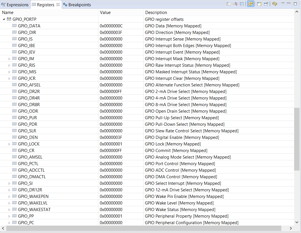
    It is in GPIO mode I assume you are configuring the Port P? If that is the case, can you please send the snapshot of Port P registers from the register Window after configuration?
  • Hi Amit

    Yes, they are configured as GPIO, here is the register information after configuration:

  • Hello Josue,

    The configuration is correct for the GPIO Port P. Did you check on both the booster pack header and the bread board header. If both headers do not work, please try with another LaunchPad to eliminate a potential device damage issue.
  • Hi Amit I tried with a diferent board (new tm4c129e crypto connected Launchpad) and the BLINK code works well (PL0 to PL5 and PP4,PP5 turns the leds on), it is possible to know why the port P of my other board is out of service???, I have only used this port when I was trying to connect the MCU to the USB3300 board.
    One more thing, the bread board header have the same problem than the boosterpack, port P does not work here neither.
  • Hello Josue,

    I have tested it on my EK-TM4C129EXL and I do not see any issues on the header nor on the bread board connector.
  • Hello Amit

    Finally I got the TM4C129 ULPI's module working with the USB3300 board from waveshare, there are some modifications that must be done:

    -In usbdenum.c:

            if(g_ui32PLLDiv == 0)
            {
                USBClockEnable(USB0_BASE, g_ui32PLLDiv, USB_CLOCK_EXTERNAL);
            }
            else
            {
                USBClockEnable(USB0_BASE, g_ui32PLLDiv, USB_CLOCK_INTERNAL);
            }
    
            //
            // Configure ULPI support.
            //
    
          if(g_ui32ULPISupport != USBLIB_FEATURE_ULPI_NONE)
            {
                USBULPIEnable(USB0_BASE);
    
                if(g_ui32ULPISupport & USBLIB_FEATURE_ULPI_HS)
                {
                    ULPIConfigSet(USB0_BASE, ULPI_CFG_HS);
                }
                else
                {
                    ULPIConfigSet(USB0_BASE, ULPI_CFG_FS);
                }
            }
            else
            {
                USBULPIDisable(USB0_BASE);
            }


    Must be replaced just with:

            //
            // Configure ULPI support.
            //
    
            if(g_ui32ULPISupport != USBLIB_FEATURE_ULPI_NONE)
            {
                // Set the PLL to USB clock divider... if using the PHY's clock
                USBClockEnable(USB0_BASE, 2, USB_CLOCK_EXTERNAL);
                USBULPIEnable(USB0_BASE);
    
                if(g_ui32ULPISupport & USBLIB_FEATURE_ULPI_HS)
                {
                    ULPIConfigSet(USB0_BASE, ULPI_CFG_HS);
                }
                else
                {
                    ULPIConfigSet(USB0_BASE, ULPI_CFG_FS);
                }
            }
            else
            {
                // Set the PLL to USB clock divider.
                USBClockEnable(USB0_BASE, g_ui32PLLDiv, USB_CLOCK_INTERNAL);
                USBULPIDisable(USB0_BASE);
            }
    

    This will force he usage of an external clock if we are going to use the ULPI module. This is better explained in this link, here the modifications are explanied to get the TM4C129e working with a USB3320, but works for me with the USB3300 board from Waveshare:

    http://robstoddard.com/ulpi.php

    The complete ccs project can be downloaded here:

    https://mega.nz/#!k8A3kKAZ!CTC25xBRMcGqZ7IE2f_TqNbZ4d9EWxK8hpzDmE5Cf98

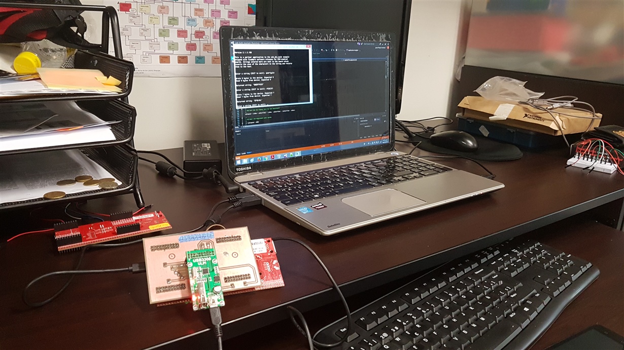
    A photo :D

    I recommend to:
    -Make a shield, connecting with cables can be annoying, 60 MHz signal with cables is not a good idea.
    -Test all the ports that are going to be used : P,B,L....

    The next step is to check the speed.

  • Hello Josue,

    Glad that you got it to work. I checked my configuration with USB ULPI and the following is the only code I needed in the application without having to modify the lower usblib layer.

    //
    // Enable the use of an external USB ULPI connected PHY or internal PHY
    // based on USB mode selection
    //
    SysCtlVCOGet(SYSCTL_XTAL_25MHZ, &ui32PLLRate);
    USBDCDFeatureSet(0, USBLIB_FEATURE_CPUCLK, &ui32SysClock);
    USBDCDFeatureSet(0, USBLIB_FEATURE_USBPLL, &ui32PLLRate);

    //
    // If High Speed Mode is requested then set ULPI option for high speed.
    //
    if(bUSBBusMode)
    {
    ui32ULPI = USBLIB_FEATURE_ULPI_HS;
    USBDCDFeatureSet(0, USBLIB_FEATURE_USBULPI, &ui32ULPI);
    }
  • Hi Amit, i will try your configuration, with my configuration I can not send more than 255 chars in each transmision, it is weird.
    the reference design for USB 3300 was no supposed to be out last week?, It will also help me a lot

    Are you sure about using:

    SysCtlVCOGet(SYSCTL_XTAL_25MHZ, &ui32PLLRate);

    In other post I found that is necesary to set 

    ui32PLLRate = 0
  • Hello Josue,

    The 255 bytes is because of the buffer size. You will need to change that as USB HS supports larger bulk size packets. I am using USB3300 with the program settings mentioned in my previous post without any issues.
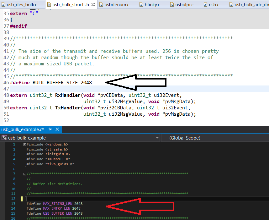
  • Do you mean changing the BULK_BUFFER_SIZE in usb_bulk_structs.h, and MAX_ENTRY_LEN on the PC side code to 512 or more??

  • Hello Josue,

    Yes. I have been using Buffer size define of 2048 with USBHS without issues.
  • Hi Amit.

    I have modified the buffer sizes in the BULK_BUFFER_SIZE on the MCU and MAX_ENTRY_LEN on the PC side to 512,1024 and 2048, but when I try to send more than 269 chars from the PC side, the code gest stuck on:

    				bResult = WriteUSBPacket(hUSB, szBuffer, ulLength, &ulWritten);//PC side code
    

    And when I tried to send more than 269 chars from the MCU to the PC i get, error 31:

    Error 31 (Uno de los dispositivos conectados al sistema no funciona.) reading from bulk IN pipe.

    this means : One of the devices connected to the system does not works...

    Everythig goes well when I send only 256 chars, Am I missing something??

  • Hello Josue

    Did you update the buffer handling in the micro-controller code? Please wait for some more time for the USBHS application code to get released on TI web.
  • I have only modified what is pointed in the images, in the usb_bluk_strucks.h (MCU side) and on the usb_bulk_example.c (PC side). those  are the "buffer handling"???

  • Hello Josue,

    I am using 1024 buffer size in the Windows example. The maximum size of bulk transfer is 512 bytes.

    I believe the issue is coming from the micro-controller side, where the data transaction is not being completed and a STALL is getting issued. I would suggest (a) waiting for some more time or (b) updating the buffer management in the application firmware.