This thread has been locked.

If you have a related question, please click the "Ask a related question" button in the top right corner. The newly created question will be automatically linked to this question.

CCS/TM4C123GH6PM: ADC help on Code Composer Studio

Part Number: TM4C123GH6PM

Tool/software: Code Composer Studio

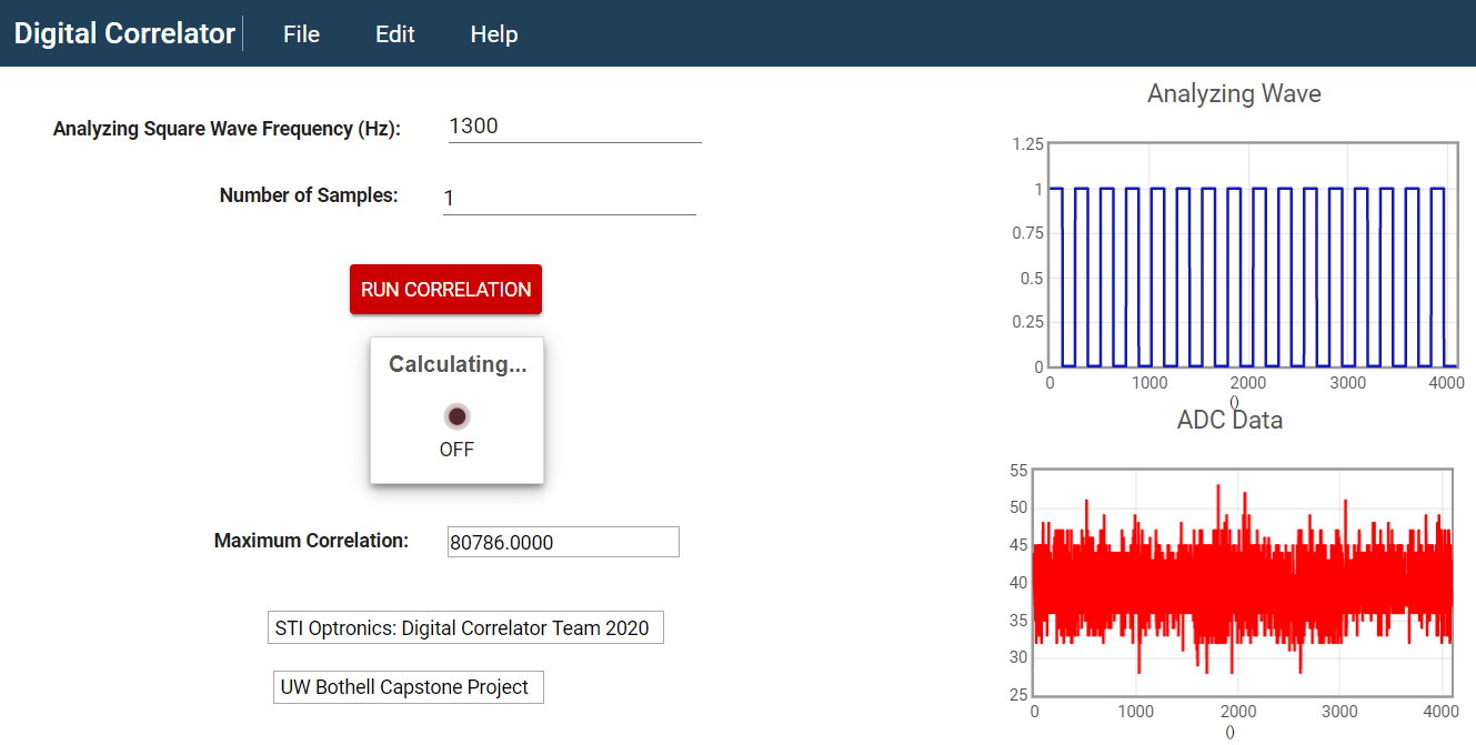
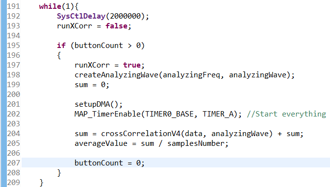
For a project, our group has to convert analog measurement into digital data. We are using the Tiva C Series TM4C123GH6PM. How do we use Code Composer Studio to not only digitize the analog values, but to store those values as well. Our plan was to connect the output of a photo diode into the analog input pins of the micro controller and use the Tiva's ADC feature to digitize the analog values. However, we need some guidance as to how we can do so in Code Composer Studio. Lab 5 of the Tiva C Series TM4C123G LaunchPad Workshop deals with the ADC however they're dealing with data from the on-chip temperature sensor. 

Thank you.

  • CB1,

    You are absolutely correct. I should have said "If you call this function without the ADC_CLOCK_RATE_FULL parameter or one of the other ADC_CLOCK_RATE_xxxx parameters, the function will default to setting the rate to 125K samples per second. 

  • Bob,

    Thank you - your positive comment welcomed & appreciated.

    As my predominantly young staff has well noted - you've gone (far) "Above & Beyond" in guiding (this) & other posters.   

    Proper understanding of these ARM-based MCUs "does" require focused effort by posters - they must recognize & accept this responsibility ... it proves "risky" (due to the number & variety of user demands) to "Count always upon Rescue by: Bob, Charles, or Ralph."   (and - as staff here notes ... beyond risky to count upon rescue by cb1 (or crüe!)

    Posters who recognize & then develop systematic "methods & procedures" to solve problems will often "Tease Out" key/critical "observations, answers & findings!"   

    By themselves ... and the resulting "gratification" is greatly empowering - certain to "further feed their motivation, capability & efficiency" - leading to "even greater" user confidence, pleasure & success...

  • ADC:

    • Regarding to your post on May 7, I want to clarify what you have stated. When you say “the proper use of this function for a 1uS sample rate is: …,” you are stating that the line of code that you have posted, ADCClockConfigSet(ADC0_BASE, ADC_CLOCK_SRC_PIOSC |ADC_CLOCK_RATE_FULL,1), is how you would set up the ADC clock to operate at the default 16MHz using the function. That is, it is the same as having that line of code commented out. Also, thank you for clarifying that the clock divisor parameter is used by the TMC129 parts only and that without the ADC_CLOCK_RATE_FULL parameter the ADC defaults to a rate of 125K samples/second.
    • Is there a reason as to why the ADC clock is independent of the system clock? Is it a hardware limitation?

    Timer

    • Earlier you’ve verified that we are correctly sampling at 332.8K samples/second by checking that the timer triggers every 3us. This is done with the function MAP_TimerLoadSet(TIMER0_BASE, TIMER_A, MAP_SysCtlClockGet() / 332800 -1). Regarding the third parameter, which is what we’re loading the timer, it is not clear to me as how this third parameter results in sampling at 332.8K samples/second or any sampling rate that we select in replace of the 332800. Since we have set the system clock to 80Mhz, MAP_SysCtlClockGet() will return 80*10^6 and we’re dividing that by 332800 and subtracting 1 which results to ~ 239.

  • Muhammad Rezuna said:
    When you say “the proper use of this function for a 1uS sample rate is: …,” you are stating that the line of code that you have posted, ADCClockConfigSet(ADC0_BASE, ADC_CLOCK_SRC_PIOSC |ADC_CLOCK_RATE_FULL,1), is how you would set up the ADC clock to operate at the default 16MHz using the function. That is, it is the same as having that line of code commented out.

    Yes.

    Muhammad Rezuna said:
    Earlier you’ve verified that we are correctly sampling at 332.8K samples/second by checking that the timer triggers every 3us. This is done with the function MAP_TimerLoadSet(TIMER0_BASE, TIMER_A, MAP_SysCtlClockGet() / 332800 -1). Regarding the third parameter, which is what we’re loading the timer, it is not clear to me as how this third parameter results in sampling at 332.8K samples/second or any sampling rate that we select in replace of the 332800. Since we have set the system clock to 80Mhz, MAP_SysCtlClockGet() will return 80*10^6 and we’re dividing that by 332800 and subtracting 1 which results to ~ 239.

    The timer loads the value 239 and counts down to zero. It fires the ADC when it reaches zero and then starts at 239 again on the next system clock. That means the ADC starts every 240 system clock cycles. With the system clock at 80MHz, the time is 240 x 12.5nS = 3.00uS, or 333.,333 samples per second. That is slightly higher than the requested sample rate. However, the next slower sample rate would be every 241 system clock cycles and that would give a rate of 331,950 samples per second.

  • Currently we have no issues collecting data from the ADC. However, we are experiencing a long execution time when we integrate our ADC algorithm with the cross-correlation algorithm. The cross-correlation algorithm, to briefly explain the process, consists of multiplying and summing the products of elements of two arrays. We tested the cross-correlation algorithm with two software-generated waves and found that the execution time was around 3 seconds. However, when we incorporate the ADC algorithm, i.e. cross-correlating where one array is software-generated and the other is the array of ADC conversions, the execution time is approximately 45 seconds. We suspect that something is occurring in the background that is slowing down or occupying the MCU in between the time that the ADC is collecting data until the start of the cross-correlation. We found that disabling the ADC interrupt, IntDisable(INT_ADC0SS0), after all of the data is captured reduced the execution time. We have also tried disabling the other peripherals such as the uDMA and the timer however that did not reduce the execute time faster than 45 seconds. What might be running in the background slowing down the execution time?


  • Put a breakpoint in your code for when the number of transfers has decremented to 1. Check to see if the ADC sequence 0 interrupt request flag is set. If it is, clear it with a call to ADCIntClear().

  • I want to clarify that when you say to "put a breakpoint in your code for when the number of transfers has decremented to 1," that you mean in the ADC interrupt routine where the last 1024 samples was just finished sampling and about to be transferred correct? In other words, all the samples have been collected by this point and we want to check if sample sequencer 0 is still requesting for conversions. I've configured the ADC, in ADCSequenceStepConfigure(), such that an interrupt is caused when the step is complete by setting the IE bit, is this what you are referring to when you mention to check to see if the ADC sequence 0 interrupt request flag is set? Which then I should call ADCIntClear() after all the samples have been collected so that the ADC stops requesting for conversions.

  • Yes, that is what I requested.

    I ran the sample code you sent earlier that did the collection. I saw that when it hit the condition "numTransfer == 1" there was an ADC sequence 0 request pending, but the ADC interrupt was disabled so it only hit this code once. Not sure what is different in your current code.

  • Thank you again for reviewing our code. How were you able to see if there was an ADC sequence 0 request pending? We used a variable to check that it does hit the condition "numTransfer == 1," which it does as you stated, but not necessarily that a request was pending. Our current has been modified since the code that I sent earlier in that we have combined the cross-correlation algorithm into the same CCS project as well as disabling the peripheral interrupts. 

    As I mentioned earlier, the execution time is approximately 45 seconds. We tested our logic with an LED to see which section of the code took-up majority of the 45 seconds. We would light the LED from one point of code and turn it off in another point to test how long that section of code took to execute. We found that majority of the execution time occurred after the Timer was enabled until the end (including the cross-correlation). We speculate that once the Timer begins, and therefore the conversions, something is still running in the background even though we've disabled the peripherals and interrupts. We checked to see if the amplitude of the incoming signal may have affected our execution time but this was not the case, at different amplitudes we are still getting a time of 45 seconds.  

    I also want to clarify all the events that are occurring within the collection of data. The timer triggers the ADC periodically which lets the ADC know when to sample. Since we set the arbitration size to 1, every time the ADC has a conversion/sample the digital value is then copied to a buffer which it then is transferred to the destination (data array). When using the ADC with the uDMA,  the uDMA causes an ADC interrupt after an arbitrary amount of data (max of 1024 - which is what we have selected) has been transferred which then switches the buffer that is being filled.  What other interrupts are occurring throughout this process? Do they still occur even after the peripherals are disabled which are then responsible for the extended execution time?4606.ADC_Capstone.zip

  • Line 154 of main.c is a delay of 37 seconds. That is probably a big part of your 45 seconds.

            SysCtlDelay(1000000000u); //Arbitrary delay. Gives the uDMA enough time to transfer the last 1024 samples before turning the ADC and Timer off
    

    3 cycles x 1,000,000,000 / 80,000,000 cycles/second  = 37 seconds

  • Reducing the value to 66500u results in only approximately 2.5ms as opposed to 37 seconds which still gives the uDMA enough time to transfer the last 1024 before the timer is stopped. With that being said, we want to be able to collect multiple samples (i.e. have the ADC collect 4096 samples, disable the timer, and repeat) for as many samples as we want but we have encountered an error.

    We have been testing our code using the GUI composer where we first select the frequency of the analyzing square wave, the wave that we are cross-correlating with the ADC conversions, and select the number of samples (i.e. how many sets of data collection we want to work with - essentially how many times we want to run/stop the ADC ) in which we then average the maximum correlation values of however many sets were selected. When we run the program once, everything is fine - 4096 samples are collected, the timer is disabled, and the maximum correlation value is calculated. When we run it a second time, after re-enabling the timer, the ADC conversions is off which skews the maximum correlation results. Interesting enough, when we run it a third time, the newly-collected 4096 samples are correct again and the maximum correlation is accurate; we find that every odd-number of runs the results are accurate and inaccurate for even-numbered of runs. 

    Note: one change we have made from the earlier code that I sent, other than the delay time inside ADCseq0Handler(), is having setupDMA() right before enabling the timer inside the while loop which is necessary because we need to re-initialize where we want the primary and alternate buffers to transfer the data after the first 4096 samples have been completed in the case for multiple run/stop of the ADC. In other words, we run the program once to collect 4096 samples and disable the timer, when we run it again we need to have re-initialize the primary and alternate structures to transfer at indices 0 and 1024 again, respectively, so that it overwrites the previous 4096 values. We are unsure as to what is affecting the ADC conversions during the even-numbered of collection. 

    The first image shows the ADC collected samples for odd-number of times ran meanwhile the second shows the ADC collected samples for even-number of times ran. Number of times ran meaning one set of samples. 

    ADC_CAP.zip

  • More context:

    Testing to see if in fact a new set of 4096 samples is collected when "Run Correlation" is clicked. For this test, I am passing in a 10mV square wave with a 10mV offset (thus having analog values approximately from 0 to 20mV) into the ADC. When I click "Run Correlation" once, 4096 samples are collected as shown under the ADC Data graph in Figure 1. I then stopped the function generator from passing in the square wave signal and expect to see that the new set of 4096 samples should approximately 0 (noise will make the ADC values nonzero).  Clicking "Run Correlation" again once the signal is turned off, it seems like the values from indices 1024-3072 were not overwritten as they still hold the previous values which can be seen in Figure 2. Not until i click "Run Correlation" again do we see an accurate ADC capture - Figure 3 shows that the data array has values of approximately 0V analog since the input is turned off. 

    We are unsure as to why the middle indices aren't updated after every click of the "Run Correlation" button. After each click, a new set of 4096 samples are collected once the timer is enabled, the timer is then disabled, and the buffers of the uDMA resets its destination address so that it starts from the beginning of the data array. Figure 4 shows what is occurring during each "Run Correlation"; when the button is clicked, buttonCount becomes greater than 0 which turns on the LED widget on the GUI letting the user know that it is entering the if-statement and calculation is occurring. 


    Figure 1:

    Figure 2:

    Figure 3: 

    Figure 4:

  • I don't see where you reset the variable "numtTimesInt" back to 1 for each time  "button > 0". (I may not have your latest code.) If you reference a static variable in the main thread and in an interrupt routine, you need to add the qualifier "volatile".

    You really need to use breakpoints, step through your code  and debug it yourself. I am happy to answer questions about how to use the TM4C123 device, but I am not supposed to debug your code for you.