This thread has been locked.

If you have a related question, please click the "Ask a related question" button in the top right corner. The newly created question will be automatically linked to this question.

LAUNCHXL-F280049C: CAN-Interface unresponsive on custom built board, works on LaunchPad with same code

Part Number: LAUNCHXL-F280049C
Other Parts Discussed in Thread: TMS320F280049C

Hey there,

I am experiencing a problem with the CAN module on a TMS320F280049C.

The board i have in front of me is working fine, I am debugging, SCI-communication with another device is working fine. On the LaunchPad (the development board I ordered) with the same exact controller, the CAN bus works without issues.

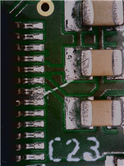
Now I debug the controller on my own board, and the program also runs without issue, stops at a breakpoint set at the pre-written function "CAN_sendMessage()", see screenshot.


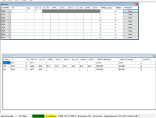
Now I am monitoring GPIO32 (CAN-Tx-Pin) to see, if there is any changes in Voltage on that Pin, since the Transceiver is doesnt Transmit messages. And there is nothing. Again, I am using Code that works fine on the LaunchPad. The only change I make is setting the Target Config to TMS320F280049C.ccxml.

I have removed the Transceiver to make sure that there is no interference on that side, with no luck. This is a work project, I am a trainee and surely not experienced.

Is there any hardware configuration, some Enable pin I am missing? The Controller has an external 20MHz oscillator on my board as well, as the CAN module needs precise timing. Is there any additional connection I have to mind?

Thank you for any help in advance!

Cheers, Chris

  • Hi Chris,

    Any reason why pins 69 (X1) and 68 (X2) are shorted?  Curious as how part is getting clocked.  You mentioned there is an external 20MHz oscillator (not crystal, correct?).  There is a different clock configuration for crystal, which uses both X1 and X2 pins, like in the case of launchpad and an external oscillator, which should only be fed to X1 pin and X2 to be left floating for the part to be clocked properly.  Is the output of the 20MHz oscillator fed to X1 and X2 on your custom board?  You should never short X1 and X2 pins.  Please refer to section 7.9.3.3 (Input Clocks and PLLs) of the datasheet for the different clocking topologies for F280049 device.

    Regards,

    Joseph

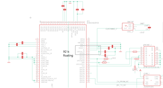
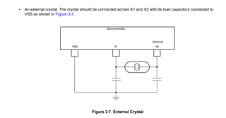
  •  This is what i've found in the datasheet. Could you refer to the datasheet you are referencing?

    3953M-AU
    SMD CLOCK OSCILLATOR

    is the oscillator I'm using.

     Is the output of the 20MHz oscillator fed to X1 and X2 on your custom board?

    Yes, it is.

     may this be the issue? meaning if i cut the short and X2 is floating, it may work?

  • Yes, that is likely a cause for CAN module not to function because of incorrect device clocking.

         1.) You need to break the trace between X1 and X2 such that X2 will be left floating and will be following a single-ended clock source (the part you are using 3953M-20-AU is a single-ended clock oscillator, not a crystal) like this topology described in the datasheet:

         2.) I do not know the CAN example code that you are running on the launchpad but inside the device initialization part of the code will be a clock set up function that you need to modify.  It is probably in this form:

        //
        // Set up PLL control and clock dividers
        //
        SysCtl_setClock(DEVICE_SETCLOCK_CFG);
    

    DEVICE_SETCLOCK_CFG may be a header definition which is typically declared as:

    //
    // Define to pass to SysCtl_setClock(). Will configure the clock as follows:
    // PLLSYSCLK = 20MHz (XTAL_OSC) * 10 (IMULT) * 1 (FMULT) / 2 (PLLCLK_BY_2)
    //
    #define DEVICE_SETCLOCK_CFG         (SYSCTL_OSCSRC_XTAL | SYSCTL_IMULT(10) |  \
                                         SYSCTL_FMULT_NONE | SYSCTL_SYSDIV(2) |   \
                                         SYSCTL_PLL_ENABLE)


    You need to change SYSCTL_OSCSRC_XTAL argument to SYSCTL_OSCSRC_XTAL_SE for single ended clock configuration, to be consistent with your clock source.

        3.) Recompile your code and load.

    Hopefully this helps with your issue.

  • Thank your for your responses, I will try your solution to the problem the moment i have a free day, I am in my exam phase right now.

    If it works, I will press the green button immediately.

  • Ok, good luck on your debug and let me know if you have other questions.  In the meantime, i'll keep this thread open until you have a chance to debug and get back to it.

  • Hey Joseph,

    Thank you for leaving the thread open!

    I have followed your instruction documented in the following screenshots, unfortunately with the same result --> the CAN_Tx_Pin (GPIO32) is not showing any change in voltage (before Initialization, it has constant 0V, after Init it changes to constant 3.3V).

    #1                                                                                     #2                                                                     #3


    #4


    full Schematic with X2 floating

    picture of X2 disconnected from X1 now, i will add a foto of the PCB as soon as I've taken a decent one.

    To add for entirety: The other functions are still working on the custom board with changed clock configuration and X2 floating, just CAN functionality on the CAN interface is still not working.

  • Chris,

    Can you elaborate what you meant by "The other functions are still working on the custom board with changed clock configuration and X2 floating, just CAN functionality on the CAN interface is still not working."  Which functions are these?

    Also noted that there is a 56K pullup on the CANTX pin.  What is it for?  Seems like the transceiver used in your custom board design supports multi-level input and has some timeout features.  It is not the same transceiver as the one used in LaunchPad and they have different specs and features.  Moreover, the CAN module has some safeguards that when multiple errors or faults occur, the module is isolated from the bus and transmit/receive functions are inhibited so that other nodes will not be affected.

    To isolate the transceiver from the picture (and avoid cutting traces), i suggest the following:

          - Use can_ex1_loopback example

          - Since main clock is now single-ended oscillator, apply  the same changes in clock setup (use SYSCTL_OSCSRC_XTAL_SE)

          - In your schematics, it seems that GPIO30 and GPIO31 (pins 98 and 99, near the corner) are unused.  Configure  CANA_TX and CANA_RX respectively as GPIO31 and GPIO30.

    The example loopback test transmits two bytes with incrementing data and it does not require a transceiver in order to function.  Transmitted data goes directly to the CAN RX buffer so transmit/receive transactions are carried out without external stimulus (so bus faults will not have any influence on the error counters).  Although data traffic is internal in the loopback example,  CAN data will come out of the CAN_TX pin, which you can observe on GPIO31 (pin 99).

    Regards,

    Joseph

  • I'm going to reply to parts of your questions quick in order to stay in touch as I am in the laboratory right now and able to try things out immediately.

    Which functions are these

    SCI interface is being used to communicate with another DSP. Its part of the code and is ensured to work as otherwise the program doesnt reach the CAN communication functions.

    Also noted that there is a 56K pullup on the CANTX pin.  What is it for?

    It must be pulled high as a Boot pin in order to boot from flash, if not in debugging. Its a weak pullup. I've had the suspicion of CAN_Tx_Pin not being able to pull it down, so we removed the Transceiver and the pullup-R from one of the yCs (there are 5 yCs on the PCB). Without luck. This is also the reason I'm not too concerned with the Transceiver, since I can monitor the Pin without (and with) Transceiver and pullup.

  • Chris,

    Ok, thanks for the quick response.  Good to know that boot and SCI are working.  I'm interested to see the results of running the CAN loopback example when you get a chance.

    Regards,

    Joseph 

  • The loopback example works! meaning there is communication on the CAN_Tx_Pin. The transceiver doesn't seem to be working, which is not the main issue right now. the weak pullup doesnt seem to have a negative effect

  • Just to be clear, you are running the example with CANA_TX as GPIO32, correct?

  • Yes, I copied the project I am currently working in and exchanged the main with the example code and have deleted all other custom source and header files except for main.

    That means that the changed libraries, that part of the project, remained the same. Including  CANA_TX as GPIO32

  • Ok, so now we know the following:

         - Device is properly clocked

         - Device is working (boot operation works and SCI can communicate)

         - Data can be monitored through CANA_TX (GPIO32), which is connected to the transceiver TXD pin using the CAN loopback example.

    How do you monitor the signal in CANA_TX pin, is it through a CAN analyzer tool?  Is it through PCAN or any other interface or oscilloscope?  If through oscilloscope, can you capture the timing duration for a '0' or a'1' data?  Just want to confirm that the bit duration is what is programmed as the CAN bit rate.  This is important to know since if the actual bit time is not as intended, error counters will accumulate and will cause a bus-off condition that will prevent the module from transmitting any further.  Note that the error counters will not accumulate during the loopback mode.  Error counters will start to accumulate only during normal CAN operation.

    Next question is regarding the actual CAN application code that you are trying to run on your custom board that you have confirmed to be working on the LaunchPad but not on your custom board.  How is the module configured and what does the CAN Module do?  It obviously transmits some data and probably expects to receive some.  Is there anything in the code that decides when the CAN will transmit data?  Are there any other nodes connected to the CAN bus (on the CANL and CANH lines on the transceiver) when your application code is running?

    Regards,

    Joseph

  • How do you monitor the signal in CANA_TX pin, is it through a CAN analyzer tool?

    Oscilloscope, I will let you know the bit timing once I get get back to the lab.

    CAN_setBitRate(CANA_BASE, DEVICE_SYSCLK_FREQ, 50000, 16);


    CAN_setupMessageObject(CANA_BASE, 3, 3,
    CAN_MSG_FRAME_STD, CAN_MSG_OBJ_TYPE_TX, 0xFFFFFFFFU,
    CAN_MSG_OBJ_NO_FLAGS | CAN_MSG_OBJ_USE_ID_FILTER, 8);

    CAN_setupMessageObject(CANA_BASE, 4, 4,
    CAN_MSG_FRAME_STD, CAN_MSG_OBJ_TYPE_TX, 0xFFFFFFFFU,
    CAN_MSG_OBJ_NO_FLAGS | CAN_MSG_OBJ_USE_ID_FILTER, 2);

    CAN_setupMessageObject(CANA_BASE, 1, 1,
    CAN_MSG_FRAME_STD, CAN_MSG_OBJ_TYPE_RX, 0,
    CAN_MSG_OBJ_RX_INT_ENABLE, 1);

    CAN_setupMessageObject(CANA_BASE, 2, 2,
    CAN_MSG_FRAME_STD, CAN_MSG_OBJ_TYPE_RX, 0,
    CAN_MSG_OBJ_RX_INT_ENABLE, 1);

    On LaunchPad before having issues I was using a CAN receive ISR to set a variable, which is checked in order to see if any messages were requested. Worked fine. I did change that to simple polling in a loop to make sure the interrupts weren't the issue.

    I can upload my project, If that helps.

  • Yes, send a snippet of your code (just the relevant CAN portions) so we can see what is being set up.  Use the insert code feature"</>Code" for better readability.  By the way, on the above setup, the CAN bit rate is set to 50kbps, is that right?  Just wanted to make sure as most of the examples are ran with 500kbps.  You can run the CAN at 50kbps, no problem with that, just wanted to confirm that it was the intention.

    Thanks,

    Joseph

  • GPIO_setPinConfig(DEVICE_GPIO_CFG_CANRXA);
    GPIO_setPinConfig(DEVICE_GPIO_CFG_CANTXA);
    
    CAN_initModule(CANA_BASE);
    
    CAN_setBitRate(CANA_BASE, DEVICE_SYSCLK_FREQ, 50000, 16);
    
    CAN_enableInterrupt(CANA_BASE, CAN_INT_IE0 | CAN_INT_ERROR |
    CAN_INT_STATUS);
    
    Interrupt_register(INT_CANA0, &canaISR);
    
    Interrupt_enable(INT_CANA0);
    CAN_enableGlobalInterrupt(CANA_BASE, CAN_GLOBAL_INT_CANINT0);
    
    CAN_setupMessageObject(CANA_BASE, 3, 3,
    CAN_MSG_FRAME_STD, CAN_MSG_OBJ_TYPE_TX, 0xFFFFFFFFU,
    CAN_MSG_OBJ_NO_FLAGS | CAN_MSG_OBJ_USE_ID_FILTER, 8);
    
    CAN_setupMessageObject(CANA_BASE, 4, 4,
    CAN_MSG_FRAME_STD, CAN_MSG_OBJ_TYPE_TX, 0xFFFFFFFFU,
    CAN_MSG_OBJ_NO_FLAGS | CAN_MSG_OBJ_USE_ID_FILTER, 2);
    
    CAN_setupMessageObject(CANA_BASE, 1, 1,
    CAN_MSG_FRAME_STD, CAN_MSG_OBJ_TYPE_RX, 0,
    CAN_MSG_OBJ_RX_INT_ENABLE, 1);
    
    CAN_setupMessageObject(CANA_BASE, 2, 2,
    CAN_MSG_FRAME_STD, CAN_MSG_OBJ_TYPE_RX, 0,
    CAN_MSG_OBJ_RX_INT_ENABLE, 1);
    
    CAN_startModule(CANA_BASE);
    
    for (;;)
    {
    
    CAN_sendMessage(CANA_BASE, 3, 8, buffer.CAN1_1);
    DEVICE_DELAY_US(1000000);
    CAN_sendMessage(CANA_BASE, 4, 2, buffer.CAN1_2);
    
    }

    The 50 kbps are intended to cut that option out as an issue source, I've read something about that in a CAN debug manual, I might change it later once things work properly.

  • There are 4 message objects that were set up and objects 3 and 4 are continuously sent.  Since objects 3 and 4 are TX objects, filtering is irrelevant here (CAN_MSG_OBJ_USE_ID_FILTER) as this would be ignored.  Are there other nodes in the CAN network that are active other than your custom board?  In CAN, whenever a message is transmitted, a receiving node is expected to send an ACK bit in response.  This would tell the module that everything went well and message got transmitted and received properly.  If there is no acknowledgment, the error counters in the CAN module would increment and at a certain error count, the transmitting CAN node will be forced to a condition as bus-off and automatically stop transmitting.

    This is probably what is happening in your case.

  • Hey Joseph, sorry for the late reply.

    I have now confirmed following: the transceivers work the way they should with LaunchPad with the code I will post later, CAN transmits by the MPU only happen on request. That should fix the uncertainty of the module going into bus-off because of ACK missing.

    Meanwhile, I've realized that the SPLIT pin (which functions as a stabilizer for recessive voltage levels of the CAN bus) on my custum board is connected to CAN_H and CAN_L via 1.5KOhm resistors, and not between 5V and GND, as should be. Could that be the issue? We are gonna try and fix that tomorrow.

    void main(void)
    {
        CarmenInit();
        stopDSP();
        continueDSP();
        int k;
        for(k=0; k<SIZE; k++)
        {
            readMEASUREframe1();
        }
        BoxPlot(SIZE, 0);
        buffer.CAN1_1[0] = speicher2[10].deviation >> 8;
        buffer.CAN1_1[1] = speicher2[10].deviation;
        buffer.CAN1_1[2] = speicher2[10].median >> 8;
        buffer.CAN1_1[3] = speicher2[10].median;
        buffer.CAN1_1[4] = speicher2[10].mean >> 8;
        buffer.CAN1_1[5] = speicher2[10].mean;
        buffer.CAN1_1[6] = speicher2[10].min >> 8;
        buffer.CAN1_1[7] = speicher2[10].min;
        buffer.CAN1_2[0] = speicher2[10].max >> 8;
        buffer.CAN1_2[1] = speicher2[10].max;
        for (;;)
        {
            if (run == 1)
            {
                CAN_sendMessage(CANA_BASE, 3, 8, buffer.CAN1_1);
                DEVICE_DELAY_US(1000000);
                CAN_sendMessage(CANA_BASE, 4, 2, buffer.CAN1_2);
                run=0;
            }
            if (run == 2)
            {
                for(k=0; k<SIZE; k++)
                {
                    readMEASUREframe1();
                }
                run=0;
            }
            DEVICE_DELAY_US(1000);
            IDLE;
        }
    }

    Here the schematic of the working CAN Transceiver:

    And here the CAN bus analyzer tool, first working on Launchpad with response, then switching to custom board to receive "Error passive" because no ACK is transmitted from yC, assumingly.

    Again, thank you for your time!

  • Hey Chris,

    Not sure about how that transceiver works but it is worth giving a try with the stabilizing resistor.  CAN_L/CAN_H has to be terminated by a 120ohm resistor, which is confirm in your schematics.

    Good luck on your debug.

    Regards,

    Joseph