Because of the holidays, TI E2E™ design support forum responses will be delayed from Dec. 25 through Jan. 2. Thank you for your patience.

This thread has been locked.

If you have a related question, please click the "Ask a related question" button in the top right corner. The newly created question will be automatically linked to this question.

LAUNCHXL-F280049C: PWMDAC Angle generator square wave

Guru 54778 points
Part Number: LAUNCHXL-F280049C
Other Parts Discussed in Thread: MOTORWARE

MotorControlSDK v2.01 Lab-is07_SpeedControl 

Enabled the PWMDAC output for angle wave form and square wave comes out J8-pin51, 100kHz even when motor was not running Thinking.

Then added angle generator code from Lab4 with similar configuration but only to output PWMDAC0 GPIO port, not to control rotor position but to confirm. It was square wave too but Lab guide Fig.28 top (yellow) signal is very angular shaped. So I check all the PWMDAC outputs for any kind of angle shape wave, all are square wave. Yet the default estimated angle output via { pwmDACData.ptrData[0] = &angleFoc_rad; } was square wave too Weary. Why does either default PWMDAC0 or adding angle generator not have angular shaped wave form?

    //
    // initialize the angle generate module
    //
    angleGenHandle = ANGLE_GEN_init(&angleGen, sizeof(angleGen));
    ANGLE_GEN_setParams(angleGenHandle, userParams.ctrlPeriod_sec);

    //
    // set DAC parameters
    //
    pwmDACData.periodMax =
            PWMDAC_getPeriod(halHandle->pwmDACHandle[PWMDAC_NUMBER_1]);


    pwmDACData.ptrData[0] = &angleGen_rad;//&angleFoc_rad;
    
__mainISR()

~~~ basic code lines ~~~~

        /* Produce Angles on PWMDAC0 output J8-pin-51 */
        ANGLE_GEN_run(angleGenHandle, estInputData.speed_ref_Hz);
        angleGen_rad = ANGLE_GEN_getAngle_pu(angleGenHandle);

        //
        // compute angle with delay compensation
        // 25µs*low pass filtered mechanical frequency estimate, rad/sec
        angleDelta_rad = userParams.angleDelayed_sf_sec *
                         estOutputData.fm_lp_rps;//fm_rps

        angleEst_rad = MATH_incrAngle(estOutputData.angle_rad,
                                            angleDelta_rad);

        angleFoc_rad = angleEst_rad;

        //
        // compute the sin/cos phasor using fast RTS function, callable assembly
        //
        phasor.value[0] = cosf(angleFoc_rad);
        phasor.value[1] = sinf(angleFoc_rad);

 Thanks for added info Confused

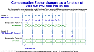
  • So much for the angle generator producing any kind of angle wave form. Text suggests only measures delay between PWM ticks and the angle being generated. The bad part being no ANGLE is being generate by FAST estimator, only 100Khz rads/second pulses. The figure below from another post asking about the delay difference Motorware motion FOC and MotorControlSDK FOC. Perhaps a good topic also being curious about rotor angle near Max Idq[0]. That seems to get entangled with Max Idq[1] causing PI controller oscillations to eventually crash trajectory. When user speed Hz gets near {user_motor_max_current_A}. 

    Allowing more time for estimator by adding 2 EPWM interrupt ticks. The same oscillation condition can occur no matter how wide the proportion and integral are widened to account for rotor inertia (kgm^2).  We typically set PI to 528k/690 for six step trapezoidal FOC, especially for heavy generator loads that may suddenly go offline. Imagine how huge AC generators might react if PID does not react fast enough to reduce input power when the load is suddenly dropped. That part of PI code is Thumb assembler, multiplies 2 uint_32t integers for target speed error and rapid duty cycle corrections in a 350µs current loop. Not bad for 120Mhz MCU with 12 bit 32Mhz ADC clock, sample rate 1.6MSPS, 2x hold time.

    Yet the SDK now set to 75µs current loop still struggles to control Max current with no load at all. The dangle of the angle may reveal truth if stable enough to compare against SVM generation. 

    //
    // compute angle with delay compensation
    // 25µs *low pass filtered mechanical frequency estimate, rad/sec
    angleDelta_rad = userParams.angleDelayed_sf_sec *
    estOutputData.fm_lp_rps;


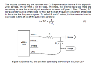
  • The PWMDAC can't be supported on LaunchPad, it must be used by adding an RC filter on the PWM output pin, and the PWMDAC is used for debugging to monitor some variables.

    You might select the right current loop frequency based on your hardware board and motor, the example lab in motor control SDK is just a reference with the TI EVM kit and the related motors, not a solution for all of the motors and hardware boars.

  • The PWMDAC can't be supported on LaunchPad, it must be used by adding an RC filter on the PWM output pin, and the PWMDAC is used for debugging to monitor some variables.

    This is not being discussed in Lab03 of any added RC filter components even being required. The PWMDAC is used to display the phase angle of FAST estimator output with tick delays added. There is no RC filter being added for Fig. 28 only previous explanation of how the angle is mathematically determined.

    Fig.28 clearly shows 4 scope channel outputs coming from PWMDAC and all GPIO outputs are on the launch pad booster headers. 

    the example lab in motor control SDK is just a reference with the TI EVM kit and the related motors,

    There is supposed to be theta phase angle output from FAST estimator ROM equations, not simply square waves. Your explanation seems to be flawed with misconceptions theta as rads/second is giving proper angle for SVM position correction data.  The idea is theta angle has slow rising slopes intersecting Id/lq sectors to constrain rotor position frames to the angle by PARK ld/lq loop controls. Theta angle as digital values can be interpreted as slope in the time constant of interrupt ticks, the SW construct. That clearly is not occurring, something is very wrong in the estimator ROM code.

  • You might select the right current loop frequency based on your hardware board and motor

    I have set all the Min/Max frequency values user.h but do notice Lab3 runs the VS frequency generator for a reduced trajectory speed. That is seemingly needed when omitting the trajectory tick control loop for speed ramp attack rate. Any way the PWMDAC angle is necessary in Lab 7 and Lab 13 to verify Park/InvPark and Vsense are keeping in phase with FAST estimator loop.

    Example of Vsense phase angle being synchronous timing to ADC samples. The Triangle wave (red) would show drift or skew away from Vsense if ADC sample timing looses synchronization. Drift of the triangle wave (red) might indicate an interrupt vector issue, motor inductance or other issues to trouble shoot.  Older ld/lq computer simulations used triangle generator feed into PARK transform, assume to keep the speed loop closed.  

  •  I do not fully understand what's your question in this thread. As replied to you, the PWMDAC is used for debugging to show the control variable as DAC. And the angle is from the angle generator and is based on the target frequency in lab03. The output waveform of the rotor angle in all of the labs using PWMDAC should be similar as Figure 28: Rotor Angle and SVGEN output waveform in the lab guide.

  • The output waveform of the rotor angle in all of the labs using PWMDAC should be similar as Figure 28: Rotor Angle and SVGEN output waveform in the lab guide.

    Yet it is only square wave when the generator is added into the interrupt handler as above code snips show. 

    angle generator and is based on the target frequency in lab03.

    The angle generator should produce a triangle wave from the FAST estimator phase angle rad/sec output at any trajectory frequency.

     it seems the angle generator is not working as it should in other labs. The angle delay (skip count) is missing in the interrupt tick speed setting. This might be why the PWM filtered delay constant reads 0x0 when mouse hovers the variable. We assert 3 skips trapezoidal FOC (20kHz) to handle larger rotor torque loads. It seems the PWM delay compensation factor is an Vsense skip count but not being updated by FAST estimator. 

  • The angle generator is only used in lab04 and lab04 with open-loop (v/f and i/f) control for hardware verification, it's not related to the FAST estimator. The angle is estimated according to the motor current, voltage, and parameters by the FAST estimator in the other labs.

  • The angle generator is only used in lab04 and lab04 with open-loop (v/f and i/f) control for hardware verification, it's not related to the FAST estimator.

    The LAB text suggests angle generator for lower frequency motors such as Fan but does not give the detail you mention here Thinking

    The angle is estimated according to the motor current, voltage, and parameters by the FAST estimator in the other labs.

    The phase angle comes from FAST estimator block diagrams but has delay filtered Rads/Sec added Lab7 - Lab13. The odd part being the delay filtered Rads/Sec value via FAST pause CCS debug mouse hover was zero. Zero value seemingly effects the angle generator output to EPWMDAC-7A  FOC_rads/sec. Perhaps we should see some PWMDAC-7A GPIO output slope due to the FAST filter delay value (Rad/Sec) relative to angle generator algorithm?  That was the purpose of posting this question. 

    The angle is estimated according to the motor current, voltage, and parameters by the FAST estimator in the other labs.

    If only the current angle offset with voltage it might produce better speed results. We sample 240µs after commutation to trigger ADC samples inductive current via trapezoidal FOC. The desecration GPIO is 75-100µs in each interrupt tick of current controller, PWM 2 ticks. This seems to be part of PI oscillations. The ADC current samples are two fast for requested trajectory Hz/sec, integral gets floppy around peak current.

    The point is we want to see better speed/torque results via SDK over that of 6 step trapezoidal FOC but it seems not possible. It would seem a combination of the two modulation methods is necessary to achieve better end results Money mouth

  • Maybe, we are discussing different things about "angle generator".  The angle generator means calling "ANGLE_GEN_run" function in lab03 and lab04 in motor control SDK. It is not used in other succeeding labs. The content of lab03 just means the v/f can be simply used for fan control if it doesn't need a faster speed response.

  • The angle generator means calling "ANGLE_GEN_run" function in lab03 and lab04 in motor control SDK.

    Yet it does not produce any slope angle at all when called in Lab7-13, how is it remotely an angle generator? Lab03 only mentions calling anglegen.c but did not give details of how it creates angle slopes. It seems the handle is not calling angle_gen_run.h as there is no angle slope being generated what so ever at 150Hz speed. The interrupt tick gives delay time to produce slope between ticks, so the angle gen algorithm is not working as logic would dictate.

    The content of lab03 just means the v/f can be simply used for fan control if it doesn't need a faster speed response.

    The point of lab03 text mentioning slow fan speed is the angle gen does not work with high speed frequency? Seemingly It is only adding delay time with no slope attributes and can only produce slope via slow frequency fan speeds, perhaps <50Hz or the angle handle is broken. There is no angle gen object code being loaded, only the typedef struct for the angle generator, broken link seems possible. Setting angle gen parameters is not an algorithm to produce generator slope. Seemingly a CPU timer might need to be invoked to produce sector angles as outlined above.

  • As replied to you, this function is not used in lab07~13, you need to refer to lab03 or lab04 to do the initialization for this function if you want to use it. A detailed description of this function can be found in the lab03 chapter in lab guide.

    v/f is used for some applications that don't need a fast speed response, and the speed range is not too high.

  • As replied to you, this function is not used in lab07~13

    The point again is need to use angle generator it in Lab7 and Lab13 but it is not working. There is no reason to use Lab3 or Lab4 with motor requires user.h inertia for kp_spd, ki_spd to stop PI from causing flux crashes. And dangerous to 100vdc inverter in open loop as Lab5 est state online can not properly handle our rotor mass >80Hz.  

    Can you please test angle generator Lab07 (add code above) verify same square wave condition PWMDAC-7A occurs via scope captures? It may be something else HAL configuration to blame. I don't comprehend why angle generator can not work in other labs unless it is bugged or needs explicit inline placement. Otherwise the SDK is a loss unable to trouble shoot current generation and PI speed issues without the angle output in Lab7. There is no foundation to work from other than current distribution becomes unstable well before PI saturation occurs. 

  • I don't understand why you need to use the angle generator in lab07 and lab13 since both labs spin the motor with a closed-loop using the angle from the FAST estimator.

    As mentioned above, please refer to lab03 and lab04 to use the angle generator and the PWMDAC if you want. 

  • I don't understand why you need to use the angle generator in lab07 and lab13 since both labs spin the motor with a closed-loop using the angle from the FAST estimator.

    Your assuming everything is working as it should with SDK labs 7-13 but clearly there are issues to be resolved. Lab3 - Lab4 are for debugging hardware issues, not debugging SW derived rotation issues especially when rotor inertia is entered into the equation. 

  • Right, the angle generator is just for verify the hardware in lab03 and lab04. The angle from the FAST estimator algorithm could be validated by using a motor embedded encoder. You might implement your method for validation as well.

  • Are you aware the HAL_PWMDAC has TBD 1/2 period 100kHz/10µs, why frequency so high? Perhaps why the PWMDAC-7A angle is more a square wave? A scope probe on Vsense ADC inputs gives more detail than PWMDAC-7B or 8A/8B  without DMA logging. Again PWMDAC-7A should produce a rotation tracking angle very close to SVM_run() commutation angle in any of the labs being added.  The idea is to experiment with PWMDAC for debug purposes. Perhaps a useful tool for monitor shoot through commands from SVM generator Force SW trips.  

    The angle from the FAST estimator algorithm could be validated by using a motor embedded encoder

    Seems more defeating to the idea of FOC sensorless commutation to put extra hardware onto motor.

  • Attached please find the technical background about PWMDAC. The frequency of PWMDAC should be far higher than the cut-off frequency of the RC filter.

  • The frequency of PWMDAC should be far higher than the cut-off frequency of the RC filter.

    Yet Lab3 Lab4 does not instruct user to add any RC filters. Perhaps text was omitted due to SW, adding RC seemingly not DSP worthy to begin with. Sure anyone can roll off PWM output (F0=1/2πRC) but that is not a proper reproduction of SVM rotation angle of FAST output. The triangle wave shown above (red) should be producible by the PWMDAC without adding capacitors via angle generator delay algorithm, to some resemblance of a triangle wave shape.

    The PWMDAC frequency (100Khz), angle generator SW has no delay adding in to the 75-100µs __mainISR() interrupt ticks being quickly overrun 10µs PWM. 

  • If you look at the angle_gen_run() algorithm (below) question why it does not update angle match value to PWDAC CMPA to directly produce triangle wave shapes. Seems to me the RC filter is synchronously masking 100Khz PWM and no link exists between the two generators.

    The PWMDAC period is supposed to link with PWM period yet it seems broken. Or the returned value has no effect on the PRD  period of PWMDAC to modulate a nearly triangle wave shape. Perhaps a software bug to pass base address of the PWMDAC handle. 

    //! \brief Links the PWMDAC_setPeriod() function to the PWM_setPeriod() function
    //!
    #define PWMDAC_getPeriod      EPWM_getTimeBasePeriod

    //! \brief Compensates for the delay introduced
    //! \brief from the time when the system inputs are sampled to when the PWM
    //! \brief voltages are applied to the motor windings.
    //! \param[in] handle The angle generator (ANGLE_COMP) handle
    //! \param[in] fm_pu The electrical speed in pu
    //! \param[in] angleUncomp_pu The uncompensated angle in pu
    static inline void ANGLE_GEN_run(ANGLE_GEN_Handle handle, const float32_t fm_pu)
    {
    ANGLE_GEN_Obj *obj = (ANGLE_GEN_Obj *)handle;

    obj->fs_pu = fm_pu;
    obj->angleDelta_pu = obj->fs_pu * obj->angleDeltaFactor;

    float32_t angle_pu = obj->angle_pu;

    //
    // increment the angle
    //
    angle_pu = angle_pu + obj->angleDelta_pu;

    //
    // mask the angle for wrap around
    // note: must account for the sign of the angle
    //
    if(angle_pu > MATH_TWO_PI)
    {
    angle_pu = angle_pu - MATH_TWO_PI;
    }
    else if(angle_pu < -MATH_TWO_PI)
    {
    angle_pu = angle_pu + MATH_TWO_PI;
    }

    //
    // account for sign
    //
    if(fm_pu < 0.0)
    {
    angle_pu = -angle_pu;
    }

    obj->angle_pu = angle_pu;

    return;
    } // end of ANGLE_GEN_run()

  • Sorry, I can't fully understand your question. The PWMDAC is used to converts any software variables into the EPWMx signals in an EPWM and can be used to view the signal represented by the variable at the outputs of the EPWMx pin through the external low-pass filters. So you need to configure the related EPWM, PWMDAC, and Angle Generator as did in lab03 or lab04, and make sure that there is an RC filter on the related PWM pins.

    Please run lab03 or lab04 and try to use the PWMDAC in these labs, that could help you to know how to use this. I can make sure there is no bug on both PWMDAC and Angle Generator.