This thread has been locked.

If you have a related question, please click the "Ask a related question" button in the top right corner. The newly created question will be automatically linked to this question.

LAUNCHXL-F280025C: DCC counters

Part Number: LAUNCHXL-F280025C
Other Parts Discussed in Thread: C2000WARE

i have a question regarding the DCC counters configuration  :


  1. Procedure I followed is from page number 63 from Reference manual tms320f28002 and here are some calculations :

PLL frequency  100MHz  that is clock1

Clock0 10MHz

             Both  Tolerance is 1 %  then I have the following counter values

            DCC error : 30

           Window : 3000

          Frequency error allowed 30

          Total error 3030

         Counter0 : 30

          Counter1:30000

          Valid0 : 2*3030 :6060

          In this case  : error detection time is around 600us and test time is 300us 


  1. Procedure taken from Continuous Monitor of the PLL Frequency With the DCC  from example calculation

   PLL frequency : 100MHz

Clk0 : 10 MHz

Resolution 0,1%

Valid min : 10

Counter1: 50000

Counter0 : 499,5


Could you please tell me why there are two procedures   ?

  • Hi Ushma,

    Please use the calculations from section "6.2.1 Configuring DCC counters" section, one in the example needs to be updated. Recommendation is to use section "Configuring DCC counters" to calculate counter configuration.

    Your calculation below is not correct, I have added my comments:

    1. Procedure I followed is from page number 623 from Reference manual tms320f28002 and here are some calculations :

    PLL frequency  100MHz  that is clock1

    Clock0 10MHz

                 Both (I am assuming Allowable Frequency tolerance is also 1%)  Tolerance is 1 %  then I have the following counter values

                DCC error : 30

               Window : 3000

              Frequency error allowed 30

              Total error 30+30=60 (DCC Error + Frequency Error allowed)

             Counter0 : 30(Window - Total Error = 3000 - 60 = 2940)

              Counter1:30000

              Valid0 : 2*3030 : 2*60 = 120

              In this case  : error detection time is around 600us and test time is 300us 

    Total time for DCC to run and compute if there is any error will be same as Window*Clock0 time = 3000*100E-9 = 300us


    We will get the Example values match the calculations defined in the section "6.2.1 Configuring DCC counters".

    Best Regards,

    Nirav

  • Hello Nirav, 

    Correct me if I am wrong but in my understanding :

    error detection time is  = countre0 goes to 0 + valid0 goes to 0 = 294+12 = 306 us 

    Sorry but i dont get why it is 600us because we start decrementing both the ountres simultaneously Right ? 

    Thanks 

    Ushma 

  • Hi Ushma,

    You are correct, time will be 300us (same as window). Already mentioned that in red.

    Best Regards,

    Nirav

  • Hello Nirav , 

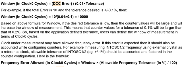
    Here we talked about two tolerances : 

    1. Tolerance 

    2. Allowable frequency tolerance 

    I have this information and would like to ask which tolerance specify the tolerance mentioned in the below picture ?

  • Hello Nirav , 

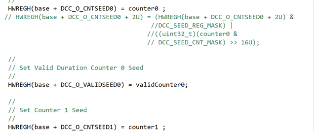
    I am using the following Code: 

    EALLOW;
        DccRegs = &Dcc0Regs;
        //
        // Set Counter 0 Seed
        //
        HWREGH(base + DCC_O_CNTSEED0) = counter0 & DCC_REG_WORD_MASK;
        HWREGH(base + DCC_O_CNTSEED0 + 2U) = (HWREGH(base + DCC_O_CNTSEED0 + 2U) &
                                              DCC_SEED_REG_MASK) |
                                             ((uint32_t)(counter0 &
                                              DCC_SEED_CNT_MASK) >> 16U);
        //
        // Set Valid Duration Counter 0 Seed
        //
        HWREGH(base + DCC_O_VALIDSEED0) = validCounter0;
        //
        // Set Counter 1 Seed
        //
        HWREGH(base + DCC_O_CNTSEED1) = counter1 & DCC_REG_WORD_MASK;
        HWREGH(base + DCC_O_CNTSEED1 + 2U) = (HWREGH(base + DCC_O_CNTSEED1 + 2U) &
                                              DCC_SEED_REG_MASK) |
                                             ((uint32_t)(counter1 &
                                              DCC_SEED_CNT_MASK) >> 16U);

    to set the values but when in debug  mode i put the break Point and try to see the counters i can see wither false value or not at all  

    Could you please help me why is it so ? 

    just for the info i am Setting These values  :

    #define VALID   240
    #define COUNT0  2880
    #define COUNT1  33000

  • It will be Allowable Frequency tolerance.

    Best Regards,

    Nirav

  • Sorry, I did not understand your question?

    Counter will be still running even though you are in debug mode, because clock to both the counters are free running.

    Best Regards,

    Nirav

  • Hello Nirav , 

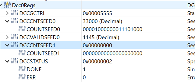
    I meant seed values of the counter , as i am loading the seed values like the following 

    DCCCNTSEED0  2880

    DCCCNTSEED1 33000

    DCCVALIDSEED0   240

    So i expect to see the same in the Registers repectively .

    But as you see in the Picture they are either not updated or falsely updated for example

    DCCCNTSEED0 is 33000

    DCCCNTSEED1 is not at all updated and DCCVALIDSEED0 is also false .My Question is why is it so ?

    Code is attached above .

    Thanks 

    Ushma 

  • Hi Ushma,

    Why are you adding +2 to the offset address inside the code "HWREGH(base + DCC_O_CNTSEED0 + 2U) "? Why dont you assign counter0seed and counter1seed value directly as you do with validcounter0 value " HWREGH(base + DCC_O_VALIDSEED0) = validCounter0;"

    Also, are you using C2000Ware driverlib function? If not, I would highly recommend using that.

    Best Regards,

    Nirav

  • Hello Nirav, 

    firstly, I tried the way you mentioned no Change in the result:

    So, I am following excatly the Code from the C200Ware/ driverlib /f28002x/driverlib/ dcc.c from there DCC_continuousMonitor fucntion  , if this what you are saying to use then yes i am already doing that .

    ALso i tried with this way using structure instead of using HWREGH : 

     DccRegs->DCCCNTSEED0.bit.COUNTSEED0 = counter0; // Loaded Counter0 Value
           DccRegs->DCCVALIDSEED0.bit.VALIDSEED = validCounter0;  // Loaded Valid Value
            DccRegs->DCCCNTSEED1.bit.COUNTSEED1 = counter1;

    but same Problem. Could you guide me further ?

    Thanks 

    Ushma 

  • Hi Ushma,

    That is strange, can you send me your code file? Your code-snippet looks fine, how does the counter0 value get assigned? Also can you also send structure of DCCREGS defined in your code. Some reason it looks like the offset is not mapped correctly.

    Best Regards,

    Nirav

  • Hello Nirav, 

    i would liek to send it personally . Could you please accept the request so thta i can send personally?

  • Hi Ushma - I just accepted the request.

    Best Regards,

    Nirav