This thread has been locked.

If you have a related question, please click the "Ask a related question" button in the top right corner. The newly created question will be automatically linked to this question.

TMS320F28377D: AMC1306 and SDFM.

Part Number: TMS320F28377D


Hi champs,

AMC1306 outputs data at clock rising edge, normally we should invert C2000 device’s SDFM clock pin so that SDFM receives data from AMC1306 at clock falling edge.

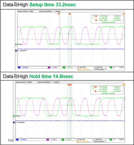
My customer doesn’t invert SDFM clock pin and conducts one experiment, the result is not good for sure. He captures the SDFM waveform and would like to understand the details, please refer to below picture. It seems that the setup and hold time for SDFM clock is enough(3-sample, 10ns) and the data just shift one bit, means that 1st clock catches wrong data, 2nd clock catches 1st data, third clock catches 2nd data, and so on.

Since the waveform looks good for SDFM module to receive data, my customer wants to know the reason he gets bad SDFM data result if not invert SDFM clock pin for data receiving. Please advise your comments on this question, thanks for help.

Regards,

Luke

  • Luke,

    If the device starts probing for SD DATA at wrong instance, it will strobe for wrong data. Once it probes wrong data filter will have incorrect results.

    Can you confirm whether inverting SD-Cx pin gives correct results?

    Regards,

    Manoj

  • Manoj,

    Yes, invert SDFM clock pin inside C2000 get correct results.

    We want to study more details. Based on the waveform, looks like the data bit shift 1-bit since SDFM catches data at clock rising edge, means,

    clock-1 : AMC1306 outputs data bit-1, DSP gets wrong data(no enough data setup time).

    clock-2 : AMC1306 outputs data bit-2, DSP gets data bit-1.

    clock-3 : AMC1306 outputs data bit-3, DSP gets data bit-2...and so on.

    The digital filter should not care about 1-bit data shift, right? Then what's the reason SDFM gets incorrect result if catching data at clock rising edge, even the setup/hold time looks good for data receive?

    More information, the SDFM settings are sinc-3, OSR = 250, clock and data settings are 3-sample, this waveform is captured at DSP I/O side. Please advise your comments if any, thanks.

    Regards,

    Luke

  • Luke,

    I have never tried this experiment. What is the filter output observed for same filter setting with / without GPIO inversion?

    I also don't why you say bit-1 doesn't have enough setup time but rest would have enough. I don't think it just is 1-bit shift like you suggested.. According to AMC1306 DS, hold time is 3.5ns. Without GPIO inversion of the SD-Cx you are not meeting the timing requirement of SDFM.

    Regards,

    Manoj

  • Manoj,

    When SYSCLK is 200MHz and SD-Cx/Dx QUAL = 3-sample, the minimum setup/hold time needed for SDFM is 10ns, no matter invert or non-invert the SD-Cx pin inside C2000 devices, is this correct?

    Regards,

    Luke

  • Luke,

    Using GPIO inversion doesn't change timing requirement. So, answer to you question is YES.

    Regards,

    Manoj

  • Manoj,

    If we set SD-clock = 10MHz, OSR = 10, Filter Type = Sinc3. Then data rate of Sinc filter is 10MHz/10 = 1MHz, and latency of Sinc filter is 3/1MHz = 3us.

    When the measured voltage changes, does it mean we get correct SDFM data every 3us?

    Regards,

    Luke

  • Yes any dramatic change in analog input voltage in SD-modulator will take latency time to be correctly reflected in the filter output.

    For example: if there is short circuit condition, analog input dramatically changes whose corresponding digital filter output gets reflected after latency time of filter.

  • Manoj,

    In F2838x devices, if customers don't use "Input Qualification" circuitry in SDFM module, they still can use the method of 3-sample QUAL on SDFM pins and keep 10ns setup/hold time as we did for F2837x devices, is this correct?

    Regards,

    Luke

  • No, in F2838x devices, it is mandated to use "Input Qualification" circuitry in SDFM module. They CANNOT use 3-sample QUAL solution on SDFM pins.

    Regards,

    Manoj

  • Manoj,

    My customer migrates the firmware from F2837x to F2838x, he uses 3-sample method on F2838x and this project has been mass-produced, no problem so far.

    If my customer CANNOT use 3-sample method, it could be a big problem. What will happen to use 3-sample method on F2838x please?

    Regards,

    Luke

  • F2838x SDFM mandates you to use ASYNC option with "Input qualification in SDFM". Why was QUAL + 3 sample window option used in the first place. SDFM timing requirements you find in the datasheet were calculated for ASYNC option with input qualification mode in SDFM. Using QUAL option + 3-sample window option violates DS.

    Regards,

    Manoj