This thread has been locked.

If you have a related question, please click the "Ask a related question" button in the top right corner. The newly created question will be automatically linked to this question.

C2000 - Simulink TI F2838x C28x I2C Transmit

Other Parts Discussed in Thread: C2000WARE

Hello All,

I am using the 28388D Control Card and trying to get the I2C comm's working with Simulink Embeded coder,

I first started with the CCS C code I2C example and with modification to the data packets got this running with no problem, a very simple code with a single device with writing & reading to 5 registers in the chip. so can prove the HW is working correctly.

The final software design will be done in Simulink Embeded coder issue I am having an issue with this design. Trying to use the Embeded I2C blocks rather than using custom code/s-functions.

After generating the code and running the code on CCS and debugging, I2C is receiving messages but not sending them. 

The issue seems to be with the line "while (I2caRegs.I2CFFTX.bit.TXFFST!=0 && tx_loop<10000 )" where the TXFFST is never equal to zero. Is there something in Simulink I am missing to clear this?

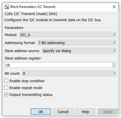
Below is the model setup 

Generated code for the blocks

if (rtb_Compare) {
    /* S-Function (c280xi2c_tx): '<S9>/I2C Transmit' incorporates:
     *  Constant: '<S3>/Control Reg2'
     */
    {
      int unsigned tx_loop= 0;
      I2caRegs.I2CFFTX.bit.TXFFIENA = 0;/* Disable Tx Fifo interrupt*/
      while (I2caRegs.I2CFFTX.bit.TXFFST!=0 && tx_loop<10000 )
        tx_loop++;
      if (tx_loop!=10000) {
        I2caRegs.I2CSAR.bit.SAR = 0;   /* Set slave address*/
        I2caRegs.I2CCNT= 1;            /* Set data length */

        /* mode:1 (1:master 0:slave)  Addressing mode:0 (1:10-bit 0:7-bit)
           free data mode:0 (1:enbaled 0:disabled) digital loopback mode:0 (1:enabled 0:disabled)
           bit count:0 (0:8bit) stop condition:1 (1:enabled 0: disabled)*/
        I2caRegs.I2CMDR.all = 28192;
        tx_loop= 0;
        while (I2caRegs.I2CFFTX.bit.TXFFST==16 && tx_loop<10000)
          tx_loop++;
        if (tx_loop!=10000) {
          I2caRegs.I2CDXR.bit.DATA = (uint8_T)IPDM_Rev_A0_P.ControlReg2_Value;
        }
      }

      I2caRegs.I2CFFTX.bit.TXFFIENA = 1;/* Enable Tx Fifo interrupt*/
      I2caRegs.I2CFFTX.bit.TXFFINTCLR = 1;/* Clear Tx interrupt flag*/
    }

    /* S-Function (fcgen): '<S6>/Function-Call Generator' incorporates:
     *  SubSystem: '<S6>/StartRead'
     */
    /* S-Function (c280xi2c_tx): '<S8>/I2C Transmit' incorporates:
     *  Constant: '<S6>/Constant1'
     */
    {
      int unsigned tx_loop= 0;
      I2caRegs.I2CFFTX.bit.TXFFIENA = 0;/* Disable Tx Fifo interrupt*/
      while (I2caRegs.I2CFFTX.bit.TXFFST!=0 && tx_loop<10000 )
        tx_loop++;
      if (tx_loop!=10000) {
        I2caRegs.I2CSAR.bit.SAR = 16;  /* Set slave address*/
        I2caRegs.I2CCNT= 1;            /* Set data length */

        /* mode:1 (1:master 0:slave)  Addressing mode:0 (1:10-bit 0:7-bit)
           free data mode:0 (1:enbaled 0:disabled) digital loopback mode:0 (1:enabled 0:disabled)
           bit count:0 (0:8bit) stop condition:0 (1:enabled 0: disabled)*/
        I2caRegs.I2CMDR.all = 26144;
        tx_loop= 0;
        while (I2caRegs.I2CFFTX.bit.TXFFST==16 && tx_loop<10000)
          tx_loop++;
        if (tx_loop!=10000) {
          I2caRegs.I2CDXR.bit.DATA = (uint8_T)IPDM_Rev_A0_P.Constant1_Value;
          IPDM_Rev_A0_B.I2CTransmit = I2caRegs.I2CSTR.all;/* output i2c status */
        } else
          IPDM_Rev_A0_B.I2CTransmit = I2caRegs.I2CSTR.all | 0x40;/* output transmit data loss status */
      } else
        IPDM_Rev_A0_B.I2CTransmit = I2caRegs.I2CSTR.all | 0x80;/* output transmit data loss status */
      I2caRegs.I2CFFTX.bit.TXFFIENA = 1;/* Enable Tx Fifo interrupt*/
      I2caRegs.I2CFFTX.bit.TXFFINTCLR = 1;/* Clear Tx interrupt flag*/
    }

    /* End of Outputs for S-Function (fcgen): '<S6>/Function-Call Generator' */
  }

Simulink HW setup

I am new to the C2000 Series & Simulink, so I hoping this is a simple fix I am missing! 

Best Regards,

Neil

  • Neil,

    Thanks for posting the block code, I'm going to loop in the I2C owner from our team to see if anything jumps out at him from the inline code.  We can pull in the MW team if we see something missing and can't figure out how to implement via the GUI.

    Can you comment on which example you used in C2000Ware that worked correctly?  This will give us something to diff with the Simulink generated code.

    Best,

    Matthew

  • Hi Matthew

    It was the i2c_ex2_eeprom project from the folder.. C2000Ware_3_04_00_00\driverlib\f2838x\examples\c28x\i2c

    Thanks

  • Neil,

    Have you enabled TX FIFO and RX FIFO to begin with? What you had attached in just a code snippet, I'm not sure you have enable FIFO as shown below. Also, what is the status of TXFFST bits when you get this error? Is TXFFST = 0?

    To use TX FIFO, you need to set

    I2CFFTX.I2CFFEN = 1

    I2CFFTX.TXFFRST = 1

    To use RX FIFO, you need to set

    I2CFFRX.RXFFRST = 1

    Regards,

    Manoj

  • Hello Manoj

    The FIFO functionality isn't necessarily needed as it will be a very low message rate,

    From what I can see in Simulink Hardware setup there isn't an option to disable/enable FIFO, Although looking at the c code generated (extract below) it seems like the default from Simulink is the enable FIFO? 

    The only options relating to the FIFO is to choose the FIFO interrupt level? (All interrupts are disabled)

    void init_I2C_GPIO(void)
    {
      EALLOW;                              /* Initial I2C GPIO pin*/
      GpioCtrlRegs.GPCPUD.bit.GPIO91 = 0;  /* Enable pull-up on GPIO91 (SDAA)*/
      GpioCtrlRegs.GPCGMUX2.bit.GPIO91 = 1;/* Configure GPIO91 as SDAA*/
      GpioCtrlRegs.GPCMUX2.bit.GPIO91 = 2; /* Configure GPIO91 as SDAA*/
      GpioCtrlRegs.GPCPUD.bit.GPIO92 = 0;  /* Enable pull-up on GPIO92 (SCLA)*/
      GpioCtrlRegs.GPCGMUX2.bit.GPIO92 = 1;/* Configure GPIO92 as SCLA*/
      GpioCtrlRegs.GPCMUX2.bit.GPIO92 = 2; /* Configure GPIO92 as SCLA*/
      EDIS;
    }
    
    void init_I2C_A(void)
    {
      /* Initialize I2C*/
      EALLOW;
      CpuSysRegs.PCLKCR9.bit.I2C_A = 1;    /* Enable pheripheral clocks for I2C */
      EDIS;
      I2caRegs.I2CMDR.bit.MST = 1;         /* Select master or slave mode*/
      I2caRegs.I2CMDR.bit.DLB = 0;         /* Enable digital loopback bit */
      I2caRegs.I2CPSC.all = 199;        /* Prescaler - need 7-12 Mhz on module clk*/
      I2caRegs.I2CCLKL = 20;               /* NOTE: must be non zero*/
      I2caRegs.I2CCLKH = 20;               /* NOTE: must be non zero*/
      I2caRegs.I2CFFTX.all |= 0x6000;      /* Enable TxFIFO mode*/
      I2caRegs.I2CFFRX.all |= 0x2000;      /* Enable RxFIFO mode*/
      I2caRegs.I2CMDR.bit.IRS = 1;         /* Take I2C out of reset*/
    }

    The TXFFST value is 2 this using a breakpoint on the while loop Line 8 on the original post code) or using the continuous refresh option (I apricate if this is changing fast the refresh option may this the value update)

    The other values for FIFO I2CFFEN & TXFFRST seem to match the says you suggest to use and I haven't modified any code that Simulink generates 

    Many Thanks,

    Neil

  • TXFFST = 2 tell me that your TXFIFO has 2 words in it. TXFFST bitfield read '0' only when TXFIFO contents are transferred. This can be achieved only by generating START condition.

    I have never used Simulink to generate I2C code. Did you check with Simulink?

    Regards,

    Manoj

  • Neil,

    Is this issue resolved? Can I close this thread?

    Regards,

    Manoj