This thread has been locked.

If you have a related question, please click the "Ask a related question" button in the top right corner. The newly created question will be automatically linked to this question.

TIDM-02007: Encoder problem

Part Number: TIDM-02007
Other Parts Discussed in Thread: C2000WARE

Hi Team,

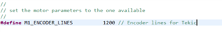
Sorry to bother you.I am currently testing the code of TIDM-02007. The level 1 test has been completed.But I found a new problem when testing LEVEL2.

I set up Level2 according to the instructions, and found that it is normal during the alignment start process, and then the motor will shake.

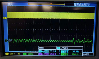
The current and voltage waveforms at the beginning of the start-up are normal, and the current waveforms are abnormal afterwards:

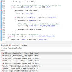
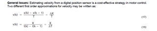
I checked the signal and found that in the ABI signal of my motor, the AB signal is normal, but the I signal is always high (5v), and the speed feedback signal Speed.Speed is also abnormal

my question is:
1. In the state of level2, if the correct I (ABI) signal cannot be obtained, will it cause the motor to run abnormally? (Or will it be related to the setting of the motor parameters?) What is your comment on this wrong current waveform?
2. If the motor cannot get the correct I signal, can it not normally run the motor such as level 4 in a closed loop (my understanding is that it will always be in the ENC_WAIT_FOR_INDEX state)

Thanks

Jenson.

  • 1. Level2 is open loop and should run without issues. It appears that you are attempting to run the motor at a higher speed than the voltage can support. Either reduce the SpeedRef or increase VqTesting.

    2. When you complete LEVEL2, you should have good quality feedback from both encoder and current sensor.

  • Hi,

    thank you for your reply.


    1.Yes, in LEVEL2, when I lower the SpeedRef, the motor can work normally without jitter. However, speed.Speed cannot follow SpeedRef. Do you have any comments on this?

    2. I ignored the problem that speed.Speed could not follow SpeedRef, and I did a level3 test. Such a problem occurred. Is this problem normal?

    3. I deleted the wrong sentence for testing and found that the motor cannot rotate normally, but iq.fbk follows iq.ref. Is the reason why the motor does not rotate related to the error in the above picture? What is your evaluation of the motor not rotating (but ABC has a waveform, the motor is similar to stalling)

    Thanks 

    Jenson

  • 1. In LEVEL2 speed.Speed has to follow the ref command. I cant tell you why you see it different. You may have to spend some time figuring out if you are watching the right parameters and what else is involved in the feedback calculation

    2. You should fully get LEVEL2 tested because feedback integrity is important for closed loop testing

    3. If the sense of rotation of motor and that of the encoder feedback are opposite (for a positive angle increment if you get negative angle slope as feedback), then the motor will stall. This is given in teh user guide. Pls review the user guide first.

  • Hi

    Thank you very much for your help.

    I'll find out why speed. Speed didn't follow the ref command. But what's wrong with my compilation at Level 3? Can there be such a mistake under normal circumstances

    Thanks 

    Jenson

  • It looks wierd, let us check.

  • You might delete the codes reported compiling error that is just for debugging. Make sure that the encoder and motor wires are connected to the launchxl and boostxl board correctly.

  • Hi Yanming,

    Got it. Thanks for your help.

    During the level2 test, does the number of pole pairs of the motor and the resolution setting of the encoder affect the estimation of speed.speed? I found that the resolution of my encoder seems to be set incorrectly. After I changed M1_ENCODER_LINES to 1200, Speed can follow speed.ref. So does M1_ENCODER_LINES set the resolution of the encoder?

    By the way, does our eqep test have a minimum RPM setting?

    Thanks

    Jenson.

  • Yes, you should set the correct motor poles and encoder lines according to the motor and encoder's spec.

    No, but the reference design can't run at zero or very low speed directly, you need to tune the related controller parameters.

  • Hi Yanming,

    Thanks for your help.

    Actually, we need to use this program to test low-speed performance. If I want to achieve a better low-speed effect, which parameters should I modify?

    Thanks.

    Jenson

  • You might tune the speed regulator gains for getting better low-speed performance, but it can't still run the motor with a very low speed. The reference design is not optimized for low speed near zero.

  • Hi Yanming,

    Understood, by speed regulator gains, you mean the PID parameters of the speed loop, right?

    Thanks 

    Jenson

  • Correct. The Kp and Ki of speed PID/PI regulator.

  • Hi Yanming,

    Thank you for your help, I am currently verifying the solution. I want to know that our feedback speed is the result of normalization. Can we make it the value of RPM? If you can, can you kindly tell me how to do it?

    Thanks

    Jenson

  • You might add a function to convert the feedback or reference speed to RPM  with the equations below since the reference design is using PU format.

    PU to RPM:  speedRef * M1(2)_BASE_FREQ * 60 / M1(2)_POLES

    RPM to PU:  RPM * M1(2)_POLES / M1(2)_BASE_FREQ / 60 

  • Thanks Yanming!

    At present, the motor can be operated at low speed through parameter optimization. But I see that our EQEP module uses the SpeedFR speed measurement method. Can we use SpeedPR to get better results? If so, do we have the corresponding code to modify?

  • The SpeedPR is for the hall sensors. No such reference code for QEP encoder till now, you might modify/add such function according to the system's requirement.

  • Hi Yanming,

    1.We now want to realize that there is a signal that can indicate the number of rotations of the motor. Can we implement this function through QEP? I see that we have the QepCountIndex parameter. When will this parameter increase? I think it doesn’t seem to increase after my motors are aligned, right? How can we implement this function, do you have any comments on this?

    2.We can now achieve low-speed operation through optimization. I want to know what calculation method our QEP uses? Formula 17 is still 18. My understanding is that Formula 18 is more accurate at low speeds.

    Thanks

    Jenson

  • Yes, both can be supported by QEP and the related software, you might refer to the example code in C2000Ware that support these two equations.  You are right, equation 18 can provide a more accurate at low speed.

    C:\ti\c2000\C2000Ware_3_04_00_00\driverlib\f28004x\examples\eqep

    The index and counter parameters don't change if the rotor is aligned without moving. The index counter will increase every rotation, please refer to the QEP chapter in TRM.

  • Hi Yanming,

    1. Regarding the Index counter, I checked ptrQEP, and it seems that there is no register indicating the value of index. I also checked the instructions in the TRM, but did not find the answer I wanted. Since I am using the QEP module for the first time, can you teach me how to get the value of index, because my client wants to get the value of index to get accurate location information.


    2. Regarding motorVars[0].posMechTheta, is this value the pu value of the mechanical position? If I want to know his specific position in a circle, I can use MechTheta*ENCODER_LINES, right?


    3. I found that my speed in the open loop state (LEVEL3) cannot reach a very low value (through the setting of Iq_ref, the lowest cannot reach 20RPM), but in the case of a closed loop speed (LEVEL4), it can reach a relatively low speed (I tried to reach 1RPM), I thought, this is the optimization that should be brought to the PID of the speed loop, right? However, I was wondering why it is impossible to run at low speed when the voltage is low?

    Thank you very much for your help.

    B.R

    Jenson

  • 1. A event flag or an interrupt will be trigged when an index appears, the user need to check the flag for counting the index by software.
    2. MechTheta*ENCODER_LINES*4

    3. Yes, it's difficult to set a right Iq_ref for running the motor at a low speed in level 3.