This thread has been locked.

If you have a related question, please click the "Ask a related question" button in the top right corner. The newly created question will be automatically linked to this question.

LAUNCHXL-F28379D: SPI receive using simulink

Part Number: LAUNCHXL-F28379D


Hello,

I am trying to receive data from an AD2S1205 resolver to digital converter via SPI. I am using the C2000 support package for simulink. There I tried the SPI receive block but failed. If I set up the SPI periphery no clock is put out at the pin. Also the CS pin won´t go low. I tried different SPI examples as well from matlab but they did not work as well on my board. The board is a launchxl-f28379d and I am using the SPI A channel. Do I need to initialize the SPI in the code/ simulink model? Or are there some other tips and tricks to get this running? 

Thank you.

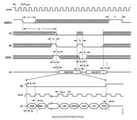
In the picture is the timing diagram of the AD2S1205

  • One of our experts will get back to you soon on this.

    Shamim

  • Florian,

    Can you comment on which set of LaunchPad pins you are using for the SPI?  If you have selected the LAUNCHXL-F28379D as the HW platform it should be picking the correct GPIOs.

    From the below picture if you are using the top SPI signals this is SPIA, if you are using the bottom that is SPIB.  In whatever SPI blocks you are using you can verify which SPI module is in use.

    Best,

    Matthew

  • Hi,

    I use the SPIA Pins. Now I get a clock out and the CS works. But there is no data received because i have to time the sample pin and rd pin correctly as well. How can I do this? I can‘t use the pulse generator with that little pulses and due to asynchronous mode the sample time has to be -1 or inf.

    Thanks 

  • Florian,

    From a quick read of the resolver DS I think you could use a GPIO from the C2000 to drive the sample signal along with using a CPU Timer to control the active/inactive.  There might be a way to do this with a PWM pin, i.e. you could precisely control the output frequency of the PWM and have the high time be equal to the sample time needed.

    I'm not sure if analog devices had some example SW on the product page that we could implement in simulink?

    Best,

    Matthew

  • Hi,

    in the attachment you will find my system setup and oscillioscope measurements from the SPI. First trace is CS, second SDO and third CLK. I connected the RD pin to CS and clamped the Sample pin low. Actually I tried to toggle the Sample pin but I did not find out how to do this correctly. As I use asynchronous subsystems I can´t use sample times in the pulse generator. Is there another way to toggle the GPIO? The ePWM pins are used already.  


  • Florian, is there a Simulink block we could put around the digital output block that will change the state every  X cycles? 

    I'm thinking how we would implement this in C code, we would create a function drive the GPIO active for "X" cycles that are required for the resolver to latch the signal, and then bring it back low.  We would call this function periodically based on the system(perhaps every control loop/at that frequency)?

    There may be a disconnect in how I understand the resolver needs to be implemented in your system as well as getting from that concept to the Simulink code.  Appreciate your feedback here.

    Best,

    Matthew

  • Hi,

    the grey block in the model is the SPI receive block. This block is called by an interrupt coming from an ePWM Signal (between 10-80khz). I only want to receive the SPI Signal what means the Resolver Signal every PWM cycle. 

    The Problem now is that I cannot find out how to toggle the Sample Pin while the interrupt with the sample time from around 20Mhz. I tried to implement C code but until now it didn´t work. 

    A function as you mentioned would probably the answer. Maybe you can figure out how I can implement that function into the interrupt routine to toggle the GPIO with the 20Mhz frequency.

    Thanks an best regards,

    Florian

  • Florian,
    I'm going to ask the MW team to take a look and comment.

    Best,

    Matthew

  • Hi Florian,

    I am not sure if I fully understand the issue here. But if you want to set GPIO first and then get the SPI Receive to work, you can use the function-call split. The first action of the function-call would be the GPIO set, then SPI Rx, and finally GPIO reset. 

    Here is a shipping example where the function-call is used.

    c28x_spi_eeprom_interrupt/Write EEPROM Data

    Regards,

    Venkatesh C