This thread has been locked.

If you have a related question, please click the "Ask a related question" button in the top right corner. The newly created question will be automatically linked to this question.

TMS320F280025: Firmware checksum

Part Number: TMS320F280025
Other Parts Discussed in Thread: UNIFLASH, C2000WARE

Hi

I am working with TMS320F280025. I need to calculate a CRC of firmware store in flash in order to make sure integrity of code before start to run it. I have several questions.

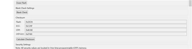
1. How to find a single CRC golden value of a compiled code for entire flash sectionin CCS

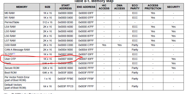
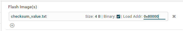
2. How to burn below item to OTP using uni flash in our production ?

    a. model number (fix value)

    b. Serial number of the product (it will change)

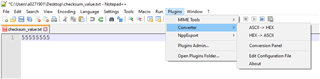
    c. Gold CRC value of firmware(fix value)

3. What is CRC calculation method e.g. CRC8, CRC16, CRC32 for compiler to calculate golden value?

4.CRC calculation is LSB-first implementations/ MSB-first implementations?

BR

HK Woo

  • Hi,

    I am checking with the compiler team and flash expert for the response. will get back to you as soon as possible.

    Thanks

    Aravindhan 

  • HK Woo,

    There is no any application-usable OTP space available on this device.  Do you mean to program this to a dedicated flash location instead?

    Please note:  I would suggest to dedicate a 128-bit location (8 words aligned on a 128-bit boundary) in flash even if your a + b + c are less than 8 words. 

    Reason: A 8-bit ECC gets calculated for every 64-bits of the flash data.  Each address location in ECC space contains ECC data for two 64-bits of the flash main array (16-bits of ECC = 8-bit ECC of lower 64-bits and 8-bit ECC of upper 64-bits).  

    I will let Aravindhan to close with our compiler team on checksum generation.

    Thanks and regards,

    Vamsi

  • Also, you might want to take a look at section 8.9.1 and section 8.9.2 in C28x Assembly Language Tools guide (https://www.ti.com/lit/pdf/spru513).

    Section 8.9.2 might be of specific interest for you.  It helps to generate CRC over memory ranges and store the result in an output section.

    Regarding the serial number of the product that you mentioned as it would change: What exact help are you looking for here?  Uniflash programs whatever is there in the image.  How do you plan to make it as part of the image?  Couple of thoughts that may help you:

    1. Allocate separate 128-bit locations for fix values and non-fix values.  This way, you can include fix values as part of the main image.

    2. For non-fix value (like the serial number) that may change for every device as you indicated: You might want to consider programming it separately from the rest of the image. Since it is only one location that you need to program, it is easy to accomplish it by populating it in a binary file and loading it using Uniflash.  Value goes in to the binary file and you can provide the target address to the Uniflash.

    Thanks and regards,
    Vamsi

  • HK Woo,

    I got your message in the email - The OTP that you see in DS is for DCSM security configuration purpose. It can't be used for any other purpose.

    Thanks and regards,

    Vamsi

  • Vamsi

    TI's document make me very confused. Please find below image

    Please explain that what is meaning of USER OTP. It is very confused. Furthermore, you suggest to use Flash to store CRC golden sample. I have question about it. Does it affect the CRC value if I put it in my firmware use #pragam CODE_SECTION detective. For example, CRC golden sample of my firmware is 0x0023F30A from CCS (still waiting a reply from TI, how to get it from CCS) and then I put the value to my firmware with below code

    #pragam CODE_SECTION (crc_goldenValue, "USER_DATA") //where USER_DATA length is 1

    uint32_t crc_goldenValue = 0x0023F30A;

    If I am correct in code, does it change CRC golden value from 0x0023F30A to other value?

    BR

    HK Woo

  • HK Woo,

    Sorry about that.  I agree that it is confusing (one may understand that it is dedicated to DCSM only if they read TRM). I will forward your feedback to our datasheet team to modify it as DCSM User OTP.

    Regarding your query on CRC value changing by placing it in flash space: You sounded there is already an active post on it- You can continue to discuss there.  If that is not the case, I can assign this to our compiler team to help you further.

    Please note: I am out of office and hence I will ask our team to help you further.

    Thanks and regards,
    Vamsi

  • Vamsi

    I don't understand your meaning on CRC issue. Does it mean that someone from TI will followup my case. Is it correct?

  • HK Woo,

    I thought you have another active post on your CRC question.  I got it now.  Our compiler team will help answer your question.  I assigned this post to them.

    Thanks and regards,
    Vamsi

  • Vamsi

    I don't have other post on CRC question. Please help to assign someone from TI to answer my question as soon as possible.

    Regarding to CRC question, did I explain clearly so that you can tell my question to TI compiler team.

    Thanks

    BR

  • HK Woo,

    Yes, I already assigned the post to our compiler team a few hours ago.  

    I got your question.  If our compiler team needs any clarification, they will let you know. 

    Thanks and regards,

    Vamsi

  • HK,

    I think the VCRC module on the F28002x will be the best option to calculate and check the flash CRC in your application.  In terms of storing the CRC golden value to flash, and it impacting the CRC; I would recommend excluding that section from the check.  Keep in mind that the flash has dual bit detect and single bit correct ECC every 128-bits, so this could be used as a safeguard that the CRC value is good.

    I would look at this application note that talks about the different CRC engines on C2000 MCUs.

    The F28002x series of MCUs has the VCRC module.  There is a coding example in C2000Ware here C:\ti\c2000\C2000Ware_3_04_00_00\libraries\dsp\VCU\c28\examples\crc\  You can use the 2838x_vcrc_*** examples on this device

    Best,

    Matthew

  • Hi Matthew

    Nice to work with you again. I wish that you remember me. I am one ask TI PLC IC library for TMS320F280025. Actually, the question is for same project.

    Regarding to Flash checking, I prefer to write our own function. It is because the application was going to apply IEC60730. It is necessary to demonstrate to agency flash checking function is OK. We need to do a co-test with them  step by step in debug mode e.g. using CCS. If we are using TI function, I am not familiar to mechanism and hence it is not easy for me to demonstrate to agency since I don't know the mechanism and no detail document to show to agency.

    Based on above reason. I still prefer to write our own flash CRC32 function. I have problems as below

    1. CCS seems that it use CRC16 instead of CRC32 based on-chip-tool in CCS

    2. You mentioned that CRC golden value impacts CRC. Actually, my approach for the CRC gold value storage is that

       a. Re-arrange linker command file in order to reserve flash address from 0x8FF0 to 0x8FF1 (32 bits) link command file for storage with below

          MEMORY

          { ......

                     CRC_STORAGE : origin = 0x08FF0, length = 0x00001

           .....}

           SECTIONS

           {.....

                  crc_value : > CRC_STORAGE

       b. Using below code

           #pragam CODE_SECTION (crc_goldenValue, "crc_value ") //where length is 1

           uint32_t crc_goldenValue = 0x0023F30A; // by any  mean to get the value e.g. from CCS or ????. The CRC      

                                                                               // value is from 0x08000 to 0x8FEF

        c. In application code

            uint32_t *crc_pr = volatile uint32_t *ram_address_pr = (volatile uint32_t *)0x08FF0

            uint32_t crc_Value = *crc_pr

            Then write a CRC32 application which compute CRC32 from 0x08000 to 0x8FEF

        If there is any update on firmware, need to get a new CRC32 golden by any mean and then update crc_goldenValue  to new one.

    Above is my approach. I don't know that the approach is workable or not.

  • HK,

    Good to hear from you again, I hope things are progressing well for you on your system.

    Your approach in #2 sounds reasonable to me. 

    I'm not clear if there is further action you need from the TI side here, is there still some issue with the CRC generation that needs to be addressed?  Let me know.

    Best,

    Matthew

  • Matthew

    I need TI further help on below items.

    1. How to get CRC32 golden value from 0x08000 to 0x08FE? I cannot find a way to get it..I have try to use hex2000 to convert .out file to Intel format hex file and the write a script to calculate CRC32 by myself.However  the content of hex seems not match to CCS memory browser e.g. Content of  0x008000 is 004A BAFE in memory brower.However I cannot find any in hex file.

    2. CRC value  of the firmware will impact or not after I update crc_goldenValue in #2b. If it is true, how to store it to CRC_STORAGE?

    3. Is it necessary to disable interrupt during read flash?

  • Hi HK,

    1. Quick question: Why are you including RAM (0x08000 to 0x08FE) for the CRC calculation?  Your final image that you want to load to flash should not have any initialized sections mapped to RAM.  If you did not map any initialized sections to RAM, you can ignore the RAM content you see in memory window after loading your application image to flash using CCS flash plugin or Uniflash.  It might be a residue of the flash tool code.  Please note: CCS flash plugin calculates 16-bit checksum only for the flash and not for RAM.

    Regarding your previous question on flash plugin CRC: Flash plugin uses 16-bit CRC (many customers asked for this and hence is chosen in CCS for all of our devices in the last 15 years).  Plugin does not support 32-bit CRC.  Also, please note, flash plugin reads entire flash space to calculate and display the checksum.  Looks like this is not an issue since you mentioned you want to implement your own CRC calculation method.  

    2. You might want to separate the CRC from your main image.  Program your application image.  Then program the CRC value separately.  This way it will not affect your application image.  Do you update the image at runtime? Or only at production?

    3. No need to disable interrupts during flash reads.  

    Please note: I am out of office. I will be back to office on July 28th.

    Thanks and regards,
    Vamsi

  • Vamsi

    #1 a) Typo. It should be 0x080000 to 0x08FDF for application and 0x08FE0 to 0x08FFF0 reverses for user usage.

         b) Yes, I plan to write a program. However, I cannot find a way how to convert .out to readable format hex. I was

             using hex2000 to convert .out file to hex. As I mention, the content does not match to what show in memory

             browser. Please advance how to convert Intel hex format so that I can use the file to calculate CRC golden value

            myself.

    #2 Only at production, no image at runtime (next version need to update image at runtime). I am ok to write CRC golden value separately. Please advance how to do it. We are using Uniflash for production.

    BR

    HK Woo

  • Hi HK,

    Regarding the address ranges you mentioned: I believe there are more typos again. But that's ok as long as the address ranges are from flash.

    Regarding the output format:  Maybe you can try the --binary option provided for the hex2000.  Hex format will have header and other info.  Binary might be better for you.  Please try that.  Note that the binary output will not fill the holes with 0xFFFF and instead combines multiple sections.  For your checksum, since you don't need the address, it should be fine for you.  

    Regarding production vs runtime: Since it is only production time thing, you can separate the main image as I suggested previously.

    In Uniflash, you can load a binary file by giving the address in the GUI.  See below.

    Click on the browse button below.  

    Select a binary file which you can view/edit in a hex editor.  Below checksum_value.txt is an example binary file in which I have a chosen value.  Select your own file and select the Binary option shown below.

    Once you select, it will let you enter an address as shown below.  You can enter the address (in this example, I entered the flash address 0x80000) and proceed to load image.  Note that the address should be 128-bit aligned.

    Other thing to note for your scenario:  Use "Program Only" option when loading your checksum. This is to avoid erasing the previously programmed application image.

    If you want to use CLI instead of GUI, you can use command like below:

    > dslite  -c  TargetConfigurationFIle.ccxml  -e  -s  FlashDownloadSetting="Program Only" BinaryFileName.txt,  Address-in-hex

    Thanks and regards,

    Vamsi

  • Hi Vamsi

    Regarding to flash range, could you show me what is the problem I had made?

    1. Could you show me the syntax of hex2000 to generate binary. I used "hex2000 -b <name of .out file> and the content of .b00 is not readable.

    2. What is format of checksum_value.txt if I want to store the value at address 0x08FFE0?

  • Hi Hung Kai,

    You mentiond addresses 0x08FDF and 0x08FE0 - These are not Flash addresses.

    #1. I will ask our compiler team to help you on this.

    #2. Please see below.  I used Notepad++ to edit (I used hex plugin).

    Thanks and regards,
    Vamsi

  • Hi Vamsi

    #1. I need to know CCS CRC16 polynomial value as well.

    Thanks

    HK

  • Hi HK,

    Do you mean the CRC algo used in CCS flash plugin?  If yes, please send me a friendship request (hover over my name and click on "Request Friendship").  I can share the algo in the private chat.

    Thanks and regards,

    Vamsi

  • 1. Could you show me the syntax of hex2000 to generate binary.

    I believe a CCS project is used to organize and build this program.  In that case, use this post build step that invokes a utility named tiobj2bin.  That works better than directly using hex2000.

    the content of .b00 is not readable

    Because it is a binary file, you cannot view it with a typical text editor.  Please see the article An Introduction to Binary Files.  Near the end it shows one way to view a binary file.  Try something similar to that method.

    Thanks and regards,

    -George

  • Geroge

    1. I cannot find utility tiobjbin

    2. I used hex2000.exe to create arrary file and a syntax "hex2000 -a -romwidth=16 <filename>.out". The file ican be viewed by normal viewer. I wrote a our own script to calculate CRC16 value based on the <filename>.a00. However, it is not matched to the value of CRC16 from CCS and hence I am not sure the content of <filename>.a00 is correct or not. Please advance how to fix it e.g. how  CCS calculate CRC16....

    BR

    HK Woo

  • Hi HK,

    2) CCS reads entire flash including holes (erased locations) for checksum calculation. For your custom function, did you consider this?

    Thanks and regards,

    Vamsi

  • I cannot find utility tiobjbin

    I suspect you don't realize that, in my previous post, the words this post build step are a link.  Please click that link.  That article shows, in detail, how to invoke tiobj2bin as a post-build step in a CCS project.  Among those details, it gives the location of the script as 

    can be found in \ccs\utils\tiobj2bin within CCS installation

    Thanks and regards,

    -George

  • Vamsi

    That is the problem I have. I don't know that the content of hex2000 -a romwidth=16 is correct or not. There should be a mean to check it, does it match to CCS. I suppose that above command generates entire flash. It should be same as CCS.

    I think that a lot of TI customer should have a same problem as well. Please help to provide a solution to me how to do it. My project is running out of time.

    BR

    HK Woo

  • George

    What is a difference between hex2000 and tiobj2bin if I use binary format?

  • HK Woo,

    If you want to include holes (0xFFFF) in your image to match it with that of CCS checksum, you need to fill holes with 0xFFFF using the fill option in linker cmd file.

    Take a look at Table 12-1. Basic Hex Conversion Utility Options in https://www.ti.com/lit/pdf/spru513. It has the fill option.

    Thanks and regards,
    Vamsi

  • To TI team

    I am being played around the table. Please provide TI solution how to make my request happened. Please let me know that my request is clear or not. If not, please let me know.

    BR

    HK Woo

  • HK,

    Sorry for any inconvenience.  As I mentioned previously, CCS Flash plugin uses 16-bit checksum.  Flash plugin does not use 32-bit checksum - many customers requested for 16-bit checksum and hence it is used by all the customers in the last 15 years.  Based on this, you mentioned that you will develop your own checksum generator.  

    In that process, you said the checksum did not match with that of CCS flash plugin.  Hence, I suggested to use the fill option. Did that help you to match the checksum with that of CCS or not?  Please let me know.

    You can use the fill option as shown below:

    MEMORY
    {

    .

    .

    /* Flash sectors */
    FLASH0 : origin = 0x080002, length = 0x001FFE, fill = 0xFFFF /* on-chip Flash */
    FLASH1 : origin = 0x082000, length = 0x002000, fill = 0xFFFF /* on-chip Flash */

    .

    .

    }

    Below snapshots are taken from the TMS320C28x Assembly Language Tools guide https://www.ti.com/lit/pdf/spru513 

    Note: I did not receive your friendship request for sharing the checksum algo.

    Thanks and regards,

    Vamsi

  • Vamsi

    Thanks for your reply. At the moment, I am getting stuck on checksum issue over a month.

    1. It is fine for me to use CRC16 in my project

    2. I need to ensure a checksum of  converted file from .out file using any tool e.g. hex2000 and tiobjbin is correct. How to clarify it? I need to know CCS CRC16 algorithm and then write our own script to check that does the content match to CCS or not.

    3. Once Item 2 confirmed, need to modify link file to reserve a flash for CRC16 gold value storage. For example, flash 0x80000 to 0x8FFDF is for application code and 0x8FFE0 to 0x8FFF0 reserved for CRC16 gold value. With thisapproach, I have a question, does hex2000 -a -romwidth 16 <filename>.out generate all data from entire flash range 0x80000 to 0x8FFF0.

    If I don't explain my request clearly, please let me know

    BR

    HK Woo

  • Vamsi

    I tried your suggestions in 2 tests.

    Testing 1. -.Add flag --fill_value= 0xFFFFFFFF in C2000 Linker in CCS as below

                            -. Using  .out  to generate a file in array format with hex2000 -a -romwidth=16 f28000x_test_application.out 

                            -. View the content of converted file 1.a00

    Result         : hole is not filled with 0xFFFFFFFF

    Testing 2.  -. Keep the flag --fill=0xFFFFFFFF

                        - Change content of link file " .text            : >> FLASH_BANK0_SEC2 | FLASH_BANK0_SEC3 | FLASH_BANK0_SEC4, ALIGN(8), fill=0xFFFF".

                            -. Using  .out  to generate a file in array format with hex2000 -a -romwidth=16 f28000x_test_application.out 

                            -. View the content of converted file 1.a00

    Result        : hole is not filled with 0xFFFFFFFF

    Please let me that do I do a correct procedures or not.

    I tried to attached f28000x_test_application.a00 and .out for your reference but not successful. Or you can share converted array format file while holes are filled with 0xFFFFFFFF

  • What is a difference between hex2000 and tiobj2bin if I use binary format?

    If you use the default form of hex2000 -b, then you do not get what is generally considered a useful binary file.  Any gaps in memory are ignored.  To get that behavior, you must use image mode, i.e. hex2000 -b -image.  But image mode additionally requires a ROMS directive that describes the layout of memory in the system.  tiobj2bin inspects the input .out file, determines the range of memory used, then automatically generates a temporary text command file which contains the ROMS directive required by image mode.  Then hex2000 is invoked to create the binary file.

    Thanks and regards,

    -George

  • HK Woo,

    Can we get on to a webex meeting to discuss this further?  This will help to get you to a solution faster.  

    1) Fill option works - Are you using COFF format or EABI format for the output file?  Maybe you have two output files from the hex tool?  Please check.   

    2) Can you try adding -memwidth=16 along with -romwidth=16?

    3) Can you share your linker cmd file?

    Thanks and regards,

    Vamsi

  • Hi Vamsi

    It is very good idea to have Webex meeting. Please let me know that schedule of the meeting.

    Regarding to file sharing. I tried to attached the link file in the post but not successful. Please let me know how to share it to you.

    BR

    HK Woo

  • HK Woo,

    Sure, I will arrange for a call - I will try to include a compiler team member as well.

    What is your time zone? Are you based in Hong Kong? 

    Regarding file upload: Click on insert button at the bottom of your reply pane.  Then click on Image/Video/file and upload your linker cmd file (rename extension as .txt).  

    Thanks and regards,
    Vamsi

  • MEMORY
    {
       BEGIN           	: origin = 0x080000, length = 0x000002
       BOOT_RSVD		: origin = 0x00000002, length = 0x00000126
       RAMM0           	: origin = 0x00000128, length = 0x000002D8
       RAMM1            : origin = 0x00000400, length = 0x000003F8     /* on-chip RAM block M1 */
    // RAMM1_RSVD       : origin = 0x000007F8, length = 0x00000008 /* Reserve and do not use for code as per the errata advisory "Memory: Prefetching Beyond Valid Memory" */
    
    /* RAMLS4           : origin = 0x0000A000, length = 0x00000800
       RAMLS5           : origin = 0x0000A800, length = 0x00000800
       RAMLS6           : origin = 0x0000B000, length = 0x00000800
       RAMLS7           : origin = 0x0000B800, length = 0x00000800*/
    
       /* Combining all the LS RAMs */
       RAMLS4567        : origin = 0x0000A000, length = 0x00002000
       //RAMGS0           : origin = 0x0000C000, length = 0x000007F8
       RAMGS0           : origin = 0x0000C000, length = 0x000007D4
       RAMGS0_TEMPCOPY  : origin = 0x0000C7D4, length = 0x00000024
    
    // RAMGS0_RSVD      : origin = 0x0000C7F8, length = 0x00000008 /* Reserve and do not use for code as per the errata advisory "Memory: Prefetching Beyond Valid Memory" */
    
    
    //  FLASHBANK1       : origin = 0x00080000, length = 0x0000FFF0
    //  FLASH_BANK1_RSVD : origin = 0x0008FFF0, length = 0x00000010 /* Reserve and do not use for code as per the errata advisory "Memory: Prefetching Beyond Valid Memory" */
       BOOTROM          : origin = 0x003F0000, length = 0x00008000
       BOOTROM_EXT      : origin = 0x003F8000, length = 0x00007FC0
       RESET            : origin = 0x003FFFC0, length = 0x00000002
       /* Flash sectors */
       /* BANK 0 */
       FLASH_BANK0_SEC0  : origin = 0x080002, length = 0x000FFE	/* on-chip Flash */
       FLASH_BANK0_SEC1  : origin = 0x081000, length = 0x001000	/* on-chip Flash */
       FLASH_BANK0_SEC2  : origin = 0x082000, length = 0x001000	/* on-chip Flash */
       FLASH_BANK0_SEC3  : origin = 0x083000, length = 0x001000	/* on-chip Flash */
       FLASH_BANK0_SEC4  : origin = 0x084000, length = 0x001000	/* on-chip Flash */
       FLASH_BANK0_SEC5  : origin = 0x085000, length = 0x001000	/* on-chip Flash */
       FLASH_BANK0_SEC6  : origin = 0x086000, length = 0x001000	/* on-chip Flash */
       FLASH_BANK0_SEC7  : origin = 0x087000, length = 0x001000	/* on-chip Flash */
       FLASH_BANK0_SEC8_9_10  : origin = 0x088000, length = 0x003000	/* on-chip Flash */
       //FLASH_BANK0_SEC8  : origin = 0x088000, length = 0x001000	/* on-chip Flash */
       //FLASH_BANK0_SEC9  : origin = 0x089000, length = 0x001000	/* on-chip Flash */
       //FLASH_BANK0_SEC8_9: origin = 0x088000, length = 0x002000	/* on-chip Flash */
       //FLASH_BANK0_SEC10 : origin = 0x08A000, length = 0x001000	/* on-chip Flash */
       FLASH_BANK0_SEC11 : origin = 0x08B000, length = 0x001000	/* on-chip Flash */
       FLASH_BANK0_SEC12 : origin = 0x08C000, length = 0x001000	/* on-chip Flash */
       FLASH_BANK0_SEC13 : origin = 0x08D000, length = 0x001000	/* on-chip Flash */
       FLASH_BANK0_SEC14 : origin = 0x08E000, length = 0x001000	/* on-chip Flash */
       FLASH_BANK0_SEC15 : origin = 0x08F000, length = 0x000FF0	/* on-chip Flash */
    // FLASH_BANK0_SEC15_RSVD     : origin = 0x08FFF0, length = 0x000010  /* Reserve and do not use for code as per the errata advisory "Memory: Prefetching Beyond Valid Memory" */
    
    }
    
    
    SECTIONS
    {
       codestart        : > BEGIN, ALIGN(8)
       .text            : >> FLASH_BANK0_SEC2 | FLASH_BANK0_SEC3 | FLASH_BANK0_SEC4 | FLASH_BANK0_SEC5,   ALIGN(8)
       .cinit           : > FLASH_BANK0_SEC1,  ALIGN(8)
       .switch          : > FLASH_BANK0_SEC1,  ALIGN(8)
       .reset           : > RESET,                  TYPE = DSECT /* not used, */
    
       .stack           : > RAMM1
    
       .init_array      : > FLASH_BANK0_SEC1,  ALIGN(8)
       .bss             : > RAMLS4567
       .bss:output      : > RAMLS4567
       .bss:cio         : > RAMGS0
       .const           : > FLASH_BANK0_SEC1,  ALIGN(8)
       .data            : > RAMLS4567
       .sysmem          : > RAMLS4567
    
        ramgs0 : > RAMGS0
    
       /*  Allocate IQ math areas: */
       IQmath            : > RAMLS4567
       IQmathTables      : > RAMLS4567
       fsk_corr_lib_data : > RAMLS4567
       Ram_TempCopy	     : > RAMGS0_TEMPCOPY
    
       GROUP
       {
           .TI.ramfunc
           {
               -l sfra_f32_tmu_eabi.lib
           }
           ramfuncs
    
       } LOAD = FLASH_BANK0_SEC6,
             RUN = RAMLS4567,
             LOAD_START(RamfuncsLoadStart),
             LOAD_SIZE(RamfuncsLoadSize),
             LOAD_END(RamfuncsLoadEnd),
             RUN_START(RamfuncsRunStart),
             RUN_SIZE(RamfuncsRunSize),
             RUN_END(RamfuncsRunEnd),
             ALIGN(4)
    
    /*
      .TI.ramfunc      : LOAD = FLASH_BANK0_SEC1,
                      RUN = RAMGS0,
                      LOAD_START(RamfuncsLoadStart),
                      LOAD_SIZE(RamfuncsLoadSize),
                      LOAD_END(RamfuncsLoadEnd),
                      RUN_START(RamfuncsRunStart),
                      RUN_SIZE(RamfuncsRunSize),
                      RUN_END(RamfuncsRunEnd),
                      ALIGN(8)
    */
        SFRA_F32_Data    : > RAMLS4567, ALIGN = 64
    
        FPUmathTables    : > FLASH_BANK0_SEC11
    
    
        //.scratchpad      : > RAMLS4567
        //controlVariables : > RAMLS4567
    
        GROUP
        {
            isrcodefuncs
            dclfuncs
        }    LOAD = FLASH_BANK0_SEC8_9_10,
             RUN =  RAMLS4567,
             LOAD_START(isrcodefuncsLoadStart),
             LOAD_SIZE(isrcodefuncsLoadSize),
             LOAD_END(isrcodefuncsLoadEnd),
             RUN_START(isrcodefuncsRunStart),
             RUN_SIZE(isrcodefuncsRunSize),
             RUN_END(isrcodefuncsRunEnd),
             ALIGN(4)
    
    
    }
    
    
    /*
    //===========================================================================
    // End of file.
    //===========================================================================
    */
    
    Vamsi

    1. Yes, I am based on Hong Kong

    2. Please find attached file for your reference. At the moment, I still don't reserve  any space in flash from CRC golden value.

    BR

    HK Woo

  • HK Woo,

    1) Ok, I will send you the webex invite via private chat.  

    2) I see that you are no using pages in linker cmd.  So, you should have only one output.  I don't see you using the fill option in linker cmd file. Did you attach the correct one? 

    Thanks and regards,

    Vamsi

  • Vamsi

    #1 Accepted

    #2 Let us go over it during the meeting. I don't have too much experience on modification of link file for this function. That why need TI to assist me to make it happen.

  • HK Woo,

    #2. Got it. We can go through it in the meeting.

    Thanks and regards,
    Vamsi

  • Vamsi

    I received the mail about the webex schedule. I am ok with your proposal but I cannot find the link.

    HK

  • HK Woo,

    I spoke to the team and they are available on Wednesday instead of Tuesday.  I will send you the invite on Monday.   

    Thanks and regards,

    Vamsi

  • HK Woo,

    Here is the summary of the meeting with your team:

    1) You confirmed you don't want to match the build time checksum to that of the flash plugin's checksum anymore. 

    2) You mentioned you want to match the build time checksum with that of runtime checksum.

    3) For build time, you can use the linker based checksum generator explained in section 8.9 Linker-Generated CRC Tables and CRC Over Memory Ranges in https://www.ti.com/lit/pdf/spru513.

    Also, please take a look at Section 4 VCU CRC in the app note: https://www.ti.com/lit/spracr3 

    4) Here is an example for the linker cmd for checksum generation: Here is the path for the linker cmd file: C:\ti\c2000\C2000Ware_3_04_00_00\device_support\f2838x\common\cmd\2838x_FLASH_lnk_crc_cpu1.cmd

    5) Regarding your question on the HW CRC engine that you can use at runtime to generate the checksum and to match it with that of the linker generated checksum: I can loop in our CRC expert for you.  Can you open a new post so that I can assign it to our CRC expert?  It would be easy to track this on a new post for your next set of questions since the Uniflash questions discussed here are closed.

    Thanks and regards,
    Vamsi 

  • HK Woo,

    I spoke to our CRC expert now.  They also preferred a new post - please open a new post and give me the link - I will assign to our CRC expert to help you on #5 above.

    Thanks and regards,
    Vamsi