


Part Number: TMS320F28375D
Other Parts Discussed in Thread: TMDSCNCD280049C
Good morning.
I am currently implementing PFC using the F28375D.
I'm trying to suppress the Current Spike at the Zero Crossing point.
References are given below.
1. ttplpfc_F28004x firmware.
2. See "How to reduce current spikes at AC zero-crossing for totem-pole PFC"
https://www.ti.com/lit/slyt650
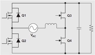
The circuit is shown below.
1. It is similar to "Figure 3" of the above document.
2. Inductor: 25mH
3. AC voltage: 220Vac single phase
4. Output voltage: 390Vdc
5. Output power: 30W
6. Switch: DMN60H3D5SK3 (Q1, Q2, Q3, Q4)
7. Switching frequency: 50kHz
8. Deadtime: 500ns
The Zero Crossing processing program is as follows. (Refers to ttplpfc_F28004x firmware)
static inline void grid_pwm_update(float32 invDuty)
{
    volatile int16 softDeadBand;
    volatile Uint16 db_tmp;
    switch(zcp.zc_position)
    {

        case zc_normalOperation:
            //Negative to Positive Zero-Crossing
//            if((grid_invSine < GRID_PWM_PZC2) && (grid_invSinePrev < 0))
            if((grid_invSine >= 0) && (grid_invSinePrev < 0))
            {
                zcp.zc_position = zc_positiveZeroCrossing1;
                invDuty = 0.004f;
                EPwm8Regs.DBCTL.bit.OUT_MODE = DBCTL_OUT_MODE_DIRECT;
                EPwm8Regs.AQCSFRC.bit.CSFA = AQCSFRC_OUT_LOW;
                EPwm8Regs.AQCSFRC.bit.CSFB = AQCSFRC_OUT_LOW;

                EPwm7Regs.DBRED.bit.DBRED = GRID_PWM_PERIOD;
                EPwm7Regs.DBFED.bit.DBFED = GRID_PWM_PERIOD;

                grid_pfc_gi.i10 = 0;
                grid_pfc_gi.i6 = 1;
                grid_curr_ref_prev = 0.00f;
            }
            //Positive to Negativ Zero-Crossing
//            else if((grid_invSine > GRID_PWM_NZC2) && (grid_invSinePrev > 0))
            else if((grid_invSine <= 0) && (grid_invSinePrev > 0))
            {
                zcp.zc_position = zc_negativeZeroCrossing1;
                invDuty = 0.004f;
                EPwm8Regs.DBCTL.bit.OUT_MODE = DBCTL_OUT_MODE_DIRECT;
                EPwm8Regs.AQCSFRC.bit.CSFA = AQCSFRC_OUT_LOW;
                EPwm8Regs.AQCSFRC.bit.CSFB = AQCSFRC_OUT_LOW;

                EPwm7Regs.DBRED.bit.DBRED = GRID_PWM_PERIOD;
                EPwm7Regs.DBFED.bit.DBFED = GRID_PWM_PERIOD;

                grid_pfc_gi.i10 = 0;
                grid_pfc_gi.i6 = 1;
                grid_curr_ref_prev = 0.00f;
            }

            break;

        ///////////////////////////////////////////////////////////////////////////////////////////
        ///////////////////////////////          Positive Cycle       /////////////////////////////
        ///////////////////////////////////////////////////////////////////////////////////////////
        case zc_positiveZeroCrossing1:
//            grid_pwm_slew++;
//            EPwm7Regs.DBRED.bit.DBRED = GRID_PWM_PERIOD;
//            EPwm7Regs.DBFED.bit.DBFED = GRID_PWM_PERIOD;
//            invDuty = 0.004f;
            invDuty = 0.004f;
            if(grid_invSine >= 0)
            {
                zcp.zc_position = zc_positiveZeroCrossing2;
//                grid_pwm_softstart = 0.0f;
            }
            break;

        case zc_positiveZeroCrossing2:
//            grid_pwm_slew++;
            invDuty = 0.004f;
            if(grid_invSine > GRID_PWM_PZC2)
            {
                zcp.zc_position = zc_positiveZeroCrossing3;
                grid_pwm_slew = CLR;
                grid_pwm_softstart = CLR;

                EPwm7Regs.DBCTL.bit.OUTSWAP = DBCTL_OUTSWAP_APATH_A_BPATH_B;    //Swap하지 않음

                grid_pfc_gi.i10 = 0;
                grid_pfc_gi.i6 = 1;
                grid_pfc_gi.Ki = 0;
            }
            break;

        case zc_positiveZeroCrossing3:
            grid_pwm_slew++;
            if(fabsf(invDuty) < 0.02f)
            {
                if(invDuty > 0) invDuty = 0.02f;
                else invDuty = -0.02f;
            }
/*
            if(fabsf(invDuty) < 0.004f)
            {
                if(invDuty > 0) invDuty = 0.004f;
                else invDuty = -0.004f;
            }
*/
            grid_pwm_softstart = grid_pwm_softstart + GRID_PWM_SOFT_GAIN;
            softDeadBand = GRID_PWM_PERIOD - grid_pwm_softstart;
            db_tmp = GRID_PWM_DB;
            if(softDeadBand < db_tmp) softDeadBand = GRID_PWM_DB;
            EPwm7Regs.DBFED.bit.DBFED = softDeadBand;

//            if((grid_pwm_slew > 3) && (grid_invSine > 0))
            if((grid_pwm_slew > GRID_PWM_SOFT_COUNT) && (grid_invSine > 0))
            {
                grid_pfc_gi.i10 = 0;
                grid_pfc_gi.i6 = 1;
                grid_pfc_gi.Ki = GRID_PFC_GI_PI_KI;
                zcp.zc_position = zc_positiveHalf;
                EPwm7Regs.DBFED.bit.DBFED = GRID_PWM_DB;
                EPwm7Regs.DBRED.bit.DBRED = GRID_PWM_DB;
                EPwm8Regs.AQCSFRC.bit.CSFA = AQCSFRC_OUT_LOW;
                EPwm8Regs.AQCSFRC.bit.CSFB = AQCSFRC_OUT_HIGH;
                grid_pwm_slew = CLR;
            }
            break;

        case zc_positiveHalf:
//            grid_pwm_slew++;
//            EPwm8Regs.AQCSFRC.bit.CSFA = AQCSFRC_OUT_LOW;
//            EPwm8Regs.AQCSFRC.bit.CSFB = AQCSFRC_OUT_HIGH;
//            EPwm7Regs.DBRED.bit.DBRED = GRID_PWM_DB;
            if((grid_invSine < GRID_PWM_NZC1) || (grid_invSine <= 0))
            {
                zcp.zc_position = zc_negativeZeroCrossing1;
                invDuty = 0.004f;
                EPwm8Regs.AQCSFRC.bit.CSFA = AQCSFRC_OUT_LOW;
                EPwm8Regs.AQCSFRC.bit.CSFB = AQCSFRC_OUT_LOW;
                EPwm7Regs.DBRED.bit.DBRED = GRID_PWM_PERIOD;
                EPwm7Regs.DBFED.bit.DBFED = GRID_PWM_PERIOD;
            }
            break;

        ///////////////////////////////////////////////////////////////////////////////////////////
        ///////////////////////////////          Negative Cycle       /////////////////////////////
        ///////////////////////////////////////////////////////////////////////////////////////////
        case zc_negativeZeroCrossing1:
//            grid_pwm_slew++;
//            EPwm7Regs.DBRED.bit.DBRED = GRID_PWM_PERIOD;
//            EPwm7Regs.DBFED.bit.DBFED = GRID_PWM_PERIOD;
//            invDuty = 0.004f;
            invDuty = 0.004f;
            if(grid_invSine <= 0)
            {
                zcp.zc_position = zc_negativeZeroCrossing2;
            }
            break;

        case zc_negativeZeroCrossing2:
//            grid_pwm_slew++;
            invDuty = 0.004f;
            if(grid_invSine < GRID_PWM_NZC2)
            {
                zcp.zc_position = zc_negativeZeroCrossing3;
                grid_pwm_slew = CLR;
                grid_pwm_softstart = CLR;

                EPwm7Regs.DBCTL.bit.OUTSWAP = DBCTL_OUTSWAP_APATH_B_BPATH_A;    //OutA, OutB Swap

                grid_pfc_gi.i10 = 0;
                grid_pfc_gi.i6 = 1;
                grid_pfc_gi.Ki = 0;
            }
            break;

        case zc_negativeZeroCrossing3:
            grid_pwm_slew++;
            if(fabsf(invDuty) < 0.004f)
            {
                if(invDuty > 0) invDuty = 0.004f;
                else invDuty = -0.004f;
            }
            grid_pwm_softstart = grid_pwm_softstart + GRID_PWM_SOFT_GAIN;
//            grid_pwm_softstart = grid_pwm_softstart + 200;
            softDeadBand = GRID_PWM_PERIOD - grid_pwm_softstart;
            db_tmp = GRID_PWM_DB;
            if(softDeadBand < db_tmp) softDeadBand = GRID_PWM_DB;
            EPwm7Regs.DBFED.bit.DBFED = softDeadBand;

            if((grid_pwm_slew > GRID_PWM_SOFT_COUNT) && (grid_invSine < 0))
            {
                grid_pfc_gi.i10 = 0;
                grid_pfc_gi.i6 = 1;
                grid_pfc_gi.Ki = GRID_PFC_GI_PI_KI;
                zcp.zc_position = zc_negativeHalf;
                EPwm7Regs.DBFED.bit.DBFED = GRID_PWM_DB;
                EPwm7Regs.DBRED.bit.DBRED = GRID_PWM_DB;
                EPwm8Regs.AQCSFRC.bit.CSFA = AQCSFRC_OUT_HIGH;
                EPwm8Regs.AQCSFRC.bit.CSFB = AQCSFRC_OUT_LOW;
                grid_pwm_slew = CLR;
            }
            break;

        case zc_negativeHalf:
//            grid_pwm_slew++;
//            EPwm8Regs.AQCSFRC.bit.CSFA = AQCSFRC_OUT_HIGH;
//            EPwm8Regs.AQCSFRC.bit.CSFB = AQCSFRC_OUT_LOW;
//            EPwm7Regs.DBRED.bit.DBRED = GRID_PWM_DB;
            if((grid_invSine > GRID_PWM_PZC1) || (grid_invSine >= 0))
            {
                zcp.zc_position = zc_positiveZeroCrossing1;
                invDuty = 0.004f;
                EPwm8Regs.AQCSFRC.bit.CSFA = AQCSFRC_OUT_LOW;
                EPwm8Regs.AQCSFRC.bit.CSFB = AQCSFRC_OUT_LOW;
                EPwm7Regs.DBRED.bit.DBRED = GRID_PWM_PERIOD;
                EPwm7Regs.DBFED.bit.DBFED = GRID_PWM_PERIOD;
            }
            break;

        case zc_defaultState:
            invDuty = 0.01f;
            EPwm8Regs.DBCTL.bit.OUT_MODE = 0;
            EPwm8Regs.AQCSFRC.bit.CSFA = AQCSFRC_OUT_LOW;
            EPwm8Regs.AQCSFRC.bit.CSFB = AQCSFRC_OUT_LOW;

            EPwm7Regs.DBRED.bit.DBRED = GRID_PWM_PERIOD;
            EPwm7Regs.DBFED.bit.DBFED = GRID_PWM_PERIOD;
            EPwm7Regs.AQCTLA.bit.CAU = TBCTR_CMP_OUTPUT_LOW;
            EPwm7Regs.AQCTLA.bit.CAD = TBCTR_CMP_OUTPUT_TOGGLE;
            EPwm7Regs.AQCTLA.bit.ZRO = TBCTR_CMP_OUTPUT_HIGH;

            computeDF22_NotchFltrCoeff(&grid_notch1, (float32)(GRID_PWM_FREQ), (float32)(grid_freq_now*2.0) , 0.25f, 0.00001f);
            computeDF22_NotchFltrCoeff(&grid_notch2, (float32)(GRID_PWM_FREQ), (float32)(grid_freq_now*2.0) , 0.25f, 0.00001f);

            if(Device_Operation == START)
            {
                zcp.zc_position = zc_normalOperation;
                grid_close_loop = START;
                grid_close_loop_first_time = SET;
            }
            break;

        default:
            zcp.zc_position = zc_defaultState;
    }
    invDuty = (float32)EPwm7Regs.TBPRD * fabsf(invDuty);
    if(invDuty == EPwm7Regs.TBPRD)
    {
        invDuty = invDuty - 1;
    }
    EPwm7Regs.CMPA.bit.CMPA = invDuty;
}
The attached waveform is the waveform at AC150V input and 320Vdc output.
AC180V or higher, 390Vdc output makes the Spike bigger and disconnects the emulator.
And malfunction of AMC1304M25DW connected by SDFM occurs.(For AC Voltage Measurement)
Also, the FET will be damaged.
Do you have any ideas to suggest?
Below is the waveform in its current state.
1. basic configuration
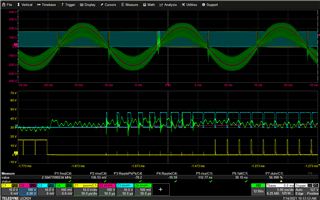
2. 50kHz Vgs Waveform
C1(Yellow): Q3 Vgs // C3(Blue): Q4 Vgs
C2(Purple): AC Volt // C4(Green): AC Current
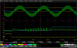
3. Line Frequency Wave form
C1(Yellow): Q1 Vgs // C3(Blue): Q2 Vgs
C2(Purple): AC Volt // C4(Green): AC Current
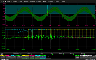
4. Vds Waveform
C1(Yellow): Q3 Vds // C3(Blue): Q4 Vds
C2(Purple): AC Volt // C4(Green): AC Current
Please let me know if you need more information.
Thank you.
