This thread has been locked.

If you have a related question, please click the "Ask a related question" button in the top right corner. The newly created question will be automatically linked to this question.

TMS320F28374S: I2C Transactions Requiring A Relatively Long Delay in Order to Safely Complete Transactions

Part Number: TMS320F28374S
Other Parts Discussed in Thread: DAC7578, TCA9555, C2000WARE

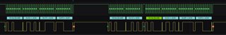
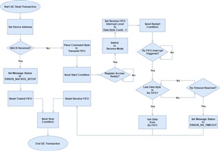
Hello, I'm working on the I2C Transactions for my system and I've noticed that in order to get my transactions to complete safely I need a delay of about 75us between each transaction in order for everything to finish properly with a Stop Condition. At a delay of about 60us or less I start to lose bus stability with bytes from previous transactions appearing in the next transaction, Missed Stop Conditions, and/or ultimately locking up the bus entirely. Is there anyone that might have any insight as to why that might be happening? With the Delay everything runs smoothly but I would like to reduce this amount of delay if possible.

Thank You!

  • Hi Ronauldus,

    Can you provide some further details on your I2C implementation? Some questions below:

    1. Is the F2837xS the master device? What I2C devices are you interfacing with? What I2C clock speed?
    2. How have you implemented the protocol? i.e. number of bytes in a write / read sequence?
      1. Maybe the write / read sequence lengths are longer than the 60us delay?
    3. Can you provide some snippets of your I2C code?

    Best,

    Kevin

  • Thank you for the response! Here's the information that you need:

    1.  Yes sorry the F2837xS is the Master Device and there are no other Masters on the I2C Bus. I'm Interfacing with a TI DAC7578, a TI TCA9555 IO Expander, and a RTCC Module. The Clock Speed is 200MHz.

    2. Read/Write Sequences

      1. DAC
        1. The Write Sequence is 3 Data Bytes total (Command/Access Byte and 2 Bytes of DAC Input)
        2. The Read Sequence is 1 Byte to Request the Data and 2 Bytes Read Back. 

      2. IO Expander
        1. The Write Sequence in 2 Data Bytes Total
        2. The Read Sequence is 1 Byte to Request and 1 Byte Back for the Pin Status of the requested Port

      3. RTCC
        1. The Write Sequence is 8 Data Bytes in Total (1 for Command/Access, 7 for the Time Parameters)
        2. The Read Sequence is 1 Data Byte for the Request and 7 Bytes Read Back

    3. Sure! Here's some I2C Code I made:
      1. /*-------------------*/
        /* I2C API Functions */
        /*-------------------*/
        
        
        /*-----------*/
        /* Variables */
        /*-----------*/
        volatile I2C_MESSAGE_STRUCT writeDAC =
        {
            .messageState = TRANSMITTING,
            .messageStatus = NO_ERROR,
            .slaveChipAddress = DAC1_SLAVE_ADDRESS,
            .dataByteCount = 2,
            .commandByte = WRITE_DAC,
            .dataByteBuffer = { 0x00U, 0x00U, 0,0,0,0,0,0,0,0,0,0,0,0,0,0 }
        };
        
        volatile I2C_MESSAGE_STRUCT readDAC =
        {
            .messageState = RECEIVING,
            .messageStatus = NO_ERROR,
            .slaveChipAddress = DAC1_SLAVE_ADDRESS,
            .dataByteCount = 2,
            .commandByte = READ_DAC,
            .dataByteBuffer = { 0,0,0,0,0,0,0,0,0,0,0,0,0,0,0,0 }
        };
        
        volatile I2C_MESSAGE_STRUCT rtcGetTimeMsg =
        {
            .messageState = RECEIVING,
            .messageStatus = NO_ERROR,
            .slaveChipAddress = RTC_SLAVE_ADDRESS,
            .dataByteCount = 7,
            .commandByte = RTC_SECONDS_INDEX,
            .dataByteBuffer = {0,0,0,0,0,0,0,0,0,0,0,0,0,0,0,0}
        };
        
        // Read the Weekday Register to Get the Oscillator Status
        volatile I2C_MESSAGE_STRUCT rtcGetOscStatusMsg =
        {
            .messageState = RECEIVING,
            .messageStatus = NO_ERROR,
            .slaveChipAddress = RTC_SLAVE_ADDRESS,
            .dataByteCount = 1,
            .commandByte = RTC_WEEKDAY_INDEX,
            .dataByteBuffer = {0,0,0,0,0,0,0,0,0,0,0,0,0,0,0,0}
        };
        
        volatile I2C_MESSAGE_STRUCT writeIOX =
        {
            .messageState = TRANSMITTING,
            .messageStatus = NO_ERROR,
            .slaveChipAddress = IO_EXPANDER_A_SLAVE_ADDRESS,
            .dataByteCount = 1,
            .commandByte = IOX_WRITE_PIN,
            .dataByteBuffer = {0,0,0,0,0,0,0,0,0,0,0,0,0,0,0,0}
        };
        
        volatile I2C_MESSAGE_STRUCT readIOX =
        {
            .messageState = RECEIVING,
            .messageStatus = NO_ERROR,
            .slaveChipAddress = IO_EXPANDER_A_SLAVE_ADDRESS,
            .dataByteCount = 1,
            .commandByte = IOX_READ_PIN,
            .dataByteBuffer = {0,0,0,0,0,0,0,0,0,0,0,0,0,0,0,0}
        };
        
        /*---------------*/
        /* I2C Functions */
        /*---------------*/
        /*---------------------------------------------------------------------------*/
        /** @brief Public I2C Read function
         * Posts the I2C Read Transaction to the I2C Manager's Mailbox
         *
         * @param [I2C_MESSAGE_STRUCT* msg] pointer to I2C message struct
         * @param [const I2C_SETTINGS_STRUCT* settings] pointer to I2C settings struct
         *
         * @returns transaction status - success (true) or failure (false)
         *//*------------------------------------------------------------------------*/
        static bool_dtc I2C_read(const I2C_SETTINGS_STRUCT* settings, volatile I2C_MESSAGE_STRUCT *msg, I2C_DEVICE_ID deviceID)
        {
            bool_dtc transactionStatus = true;
            i2cRead(settings, msg);
            DEVICE_DELAY_US(I2C_BUS_DELAY);
        
            if(NO_ERROR != msg->messageStatus)
            {
                if(WARNING_SPURIOUS_INTERRUPT == msg->messageStatus)
                {
                   ++i2cStatistics[deviceID].statsSpuriuousInterrupts;
                }
                else
                {
                   ++i2cStatistics[deviceID].statsReadsFailure;
                }
                transactionStatus = false;
            }
            else
            {
               ++i2cStatistics[deviceID].statsReadsSuccess;
            }
        
            return transactionStatus;
        }
        
        /*---------------------------------------------------------------------------*/
        /** @brief Public I2C Write function
         * Posts the I2C Write Transaction to the I2C Manager's Mailbox
         *
         * @param [I2C_MESSAGE_STRUCT* msg] pointer to I2C message struct
         * @param [const I2C_SETTINGS_STRUCT* settings] pointer to I2C settings struct
         *
         * @returns transaction status - success (true) or failure (false)
         *//*------------------------------------------------------------------------*/
        static bool_dtc I2C_write(const I2C_SETTINGS_STRUCT* settings, volatile I2C_MESSAGE_STRUCT* msg, I2C_DEVICE_ID deviceID)
        {
            bool_dtc transactionStatus = true;
        
            i2cWrite(settings, msg);
            DEVICE_DELAY_US(I2C_BUS_DELAY);
        
            if(NO_ERROR != msg->messageStatus)
            {
                if(WARNING_SPURIOUS_INTERRUPT == msg->messageStatus)
                {
                    ++i2cStatistics[deviceID].statsSpuriuousInterrupts;
                }
                else
                {
                    ++i2cStatistics[deviceID].statsWriteFailure;
                }
                transactionStatus = false;
            }
            else
            {
                ++i2cStatistics[deviceID].statsWriteSuccess;
            }
        
            return transactionStatus;
        }
        
        /*---------------*/
        /* DAC Functions */
        /*---------------*/
        /*---------------------------------------------------------------------------*/
        /** @brief Write DAC
         *
         * Public DAC Write Function to start an I2C Write Transaction
         *
         * @param [dac] pointer to an instance of DAC_STRUCT
         * @param [deviceID] The I2C Device ID
         *
         * @returns true/false based on transaction success status
         *//*------------------------------------------------------------------------*/
        bool_dtc DAC_write(DAC_STRUCT *dac, I2C_DEVICE_ID deviceID)
        {
            bool_dtc i2cTransactionSuccessful = false;
            DAC_PN partNumber = -1;
        
            switch(deviceID)
            {
                case DAC1:
                    writeDAC.slaveChipAddress = DAC1_SLAVE_ADDRESS;
                    partNumber = DAC_TI_DAC7578;
                    break;
        
                case DAC2:
                    writeDAC.slaveChipAddress = DAC2_SLAVE_ADDRESS;
                    break;
        
                default:
                    break; //Device Not Found
            }
        
            i2cTransactionSuccessful = dac_translateToI2C(dac, &writeDAC, partNumber);
        
            if(i2cTransactionSuccessful)
            {
                writeDAC.commandByte = WRITE_DAC | dac->channel;
                i2cTransactionSuccessful = I2C_write(&i2cASettings, &writeDAC, deviceID);
            }
        
            return i2cTransactionSuccessful;
        }
        
        /*---------------------------------------------------------------------------*/
        /** @brief Read DAC
         *
         * Public DAC Read Function to start an I2C Read Transaction
         *
         * @param [dac] pointer to an instance of DAC_STRUCT
         * @param [deviceID] The I2C Device ID
         *
         * @returns true/false based on transaction success status
         *//*------------------------------------------------------------------------*/
        bool_dtc DAC_read(DAC_STRUCT *dac, I2C_DEVICE_ID deviceID)
        {
            bool_dtc i2cTransactionSuccessful = false;
            DAC_PN partNumber = -1;
        
            switch(deviceID)
            {
                case DAC1:
                    readDAC.slaveChipAddress = DAC1_SLAVE_ADDRESS;
                    partNumber = DAC_TI_DAC7578;
                    break;
        
                case DAC2:
                    readDAC.slaveChipAddress = DAC2_SLAVE_ADDRESS;
                    break;
        
                default:
                    break; //Device Not Found
            }
        
            readDAC.commandByte = READ_DAC | dac->channel;
            i2cTransactionSuccessful = I2C_read(&i2cASettings, &readDAC, deviceID);
        
            if(i2cTransactionSuccessful)
            {
                i2cTransactionSuccessful = dac_translateFromI2C(dac, &readDAC, partNumber);
            }
        
            return i2cTransactionSuccessful;
        }
        
        /*---------------*/
        /* RTC Functions */
        /*---------------*/
        /*---------------------------------------------------------------------------*/
        /** @brief Initializes the RTC
         *  @param [deviceID] The I2C Device ID
         *//*------------------------------------------------------------------------*/
        bool_dtc RTC_init(I2C_DEVICE_ID deviceID)
        {
            bool_dtc i2cTransactionStatus = false;
            RTCTimeFormat defaultDate =
            {
                .year    = 0x21,
                .month   = 0x04,
                .date    = 0x25,
                .weekday = 0x01,
                .hours   = 0x10,
                .minutes = 0x30,
                .seconds = 0x30
            };
        
            i2cTransactionStatus = I2C_read(&i2cASettings, &rtcGetOscStatusMsg, deviceID);
        
            //If the I2C Read was successful and the Oscillator is NOT running
            if(i2cTransactionStatus
                && (RTC_OSCRUN_STATUS != (rtcGetOscStatusMsg.dataByteBuffer[0] & RTC_OSCRUN_STATUS)))
            {
                i2cTransactionStatus = RTC_setTime(&defaultDate, deviceID);
            }
        
            return i2cTransactionStatus;
        }
        
        /*---------------------------------------------------------------------------*/
        /** @brief read time from RTC device
         *
         * Sends the get date command to device, then converts the BCD digits to
         * integers populated into the out pointer structure.
         *
         * @param [timeStruct] pointer to an instance of RTCTimeFormat structure
         * @param [deviceID] The I2C Device ID
         *
         * @returns true/false based on transaction success status
         *//*------------------------------------------------------------------------*/
        bool_dtc RTC_getTime(RTCTimeFormat* timeStruct, I2C_DEVICE_ID deviceID)
        {
            bool_dtc i2cTransactionSuccessful = false;
        
            i2cTransactionSuccessful = I2C_read(&i2cASettings, &rtcGetTimeMsg, deviceID);
        
            if(i2cTransactionSuccessful)
            {
                i2cTransactionSuccessful = rtc_translateFromI2C(timeStruct, &rtcGetTimeMsg);
            }
        
            return i2cTransactionSuccessful;
        }
        
        /*---------------------------------------------------------------------------*/
        /** @brief set time on RTC device
         *
         * Converts the time/date data from decimal to BCD and builds it into the I2C message.
         * Then sends the message to RTC to set the new time/date.
         *
         * @param [timeStruct] pointer to an instance of RTCTimeFormat structure
         * @param [deviceID] The I2C Device ID
         *
         * @returns true/false based on transaction success status
         *//*------------------------------------------------------------------------*/
        bool_dtc RTC_setTime(RTCTimeFormat* timeStruct, I2C_DEVICE_ID deviceID)
        {
            bool_dtc i2cTransactionSuccessful = false;
        
            i2cTransactionSuccessful = rtc_translateToI2C(timeStruct, &rtcSetTimeMsg);
        
            if(i2cTransactionSuccessful)
            {
                // Disable the RTC oscillator
                i2cTransactionSuccessful = I2C_write(&i2cASettings, &rtcStopOscillatorMsg, deviceID);
        
                // Transmit the time structure to the RTC
                if(i2cTransactionSuccessful)
                {
                    i2cTransactionSuccessful = I2C_write(&i2cASettings, &rtcSetTimeMsg, deviceID);
                    Board_deviceDelayUs(I2C_BUS_DELAY); //Extra Delay Required for RTC Set Time
                }
        
                if(i2cTransactionSuccessful)
                {
                    // Enable the RTC oscillator
                    rtcStartOscillatorMsg.dataByteBuffer[RTC_SECONDS_INDEX] |= rtcSetTimeMsg.dataByteBuffer[RTC_SECONDS_INDEX];
                    i2cTransactionSuccessful = I2C_write(&i2cASettings, &rtcStartOscillatorMsg, deviceID);
                }
            }
        
            return i2cTransactionSuccessful;
        }
        
        /*---------------------------------------------------------------------------*/
        /** @brief Writes to an IO Expander on the I2C Bus
         *
         * Writes the Pin Status to the Selected Pins in the IOX_STRUCT
         *
         * @param [*iox] pointer to an instance of IOX_STRUCT
         * @param [deviceID] I2C Device ID
         *
         * @returns true/false based on transaction success status
         *//*------------------------------------------------------------------------*/
        bool_dtc IOX_write(IOX_STRUCT *iox, I2C_DEVICE_ID deviceID)
        {
            bool_dtc i2cTransactionSuccessful = false;
        
            switch(deviceID)
            {
                case IOXA:
                    writeIOX.slaveChipAddress = IO_EXPANDER_A_SLAVE_ADDRESS;
                    break;
        
                case IOXB:
                    writeIOX.slaveChipAddress = IO_EXPANDER_B_SLAVE_ADDRESS;
                    break;
        
                default:
                    break; //Device Not Found
            }
        
            writeIOX.commandByte = IOX_WRITE_PIN;
            i2cTransactionSuccessful = iox_translateToI2C(iox, &writeIOX, currentPinStatusIOX);
        
            if(i2cTransactionSuccessful)
            {
                i2cTransactionSuccessful = I2C_write(&i2cASettings, &writeIOX, deviceID);
            }
        
            return i2cTransactionSuccessful;
        }
        
        /*---------------------------------------------------------------------------*/
        /** @brief Reads from an IO Expander on the I2C Bus
         *
         * Reads the Pin Status from the Selected Pins in the IOX_STRUCT
         *
         * @param [*iox] pointer to an instance of IOX_STRUCT
         * @param [deviceID] I2C Device ID
         *
         * @returns true/false based on transaction success status
         *//*------------------------------------------------------------------------*/
        bool_dtc IOX_read(IOX_STRUCT *iox, I2C_DEVICE_ID deviceID)
        {
            bool_dtc i2cTransactionSuccessful = false;
            iox->pinStatus = IOX_PIN_DONT_CARE;
        
                switch(deviceID)
                {
                    case IOXA:
                        readIOX.slaveChipAddress = IO_EXPANDER_A_SLAVE_ADDRESS;
                        break;
        
                    case IOXB:
                        readIOX.slaveChipAddress = IO_EXPANDER_B_SLAVE_ADDRESS;
                        break;
        
                    default:
                        break; //Device Not Found
                }
        
                readIOX.commandByte = IOX_READ_PIN;
                i2cTransactionSuccessful = iox_translateToI2C(iox, &readIOX, currentPinStatusIOX);
        
                if(i2cTransactionSuccessful)
                {
                    i2cTransactionSuccessful = I2C_read(&i2cASettings, &readIOX, deviceID);
                }
        
                if(i2cTransactionSuccessful)
                {
                    i2cTransactionSuccessful = iox_translateFromI2C(iox, &readIOX);
                }
        
                return i2cTransactionSuccessful;
        }
      2. /*-------------------*/
        /* I2C HAL Functions */
        /*-------------------*/
        
        /*-----------------------------------------------------------------------------
         * Types (typedefs, structs, class declarations)
         *---------------------------------------------------------------------------*/
        /**
         * Dummy message struct to ensure currTxMsgPtr always
         * points to a valid memory location
         */
        volatile static I2C_MESSAGE_STRUCT dummyMsg =
        {
            .messageState = INACTIVE,
            .messageStatus = NO_ERROR,
            .slaveChipAddress = 1,
            .dataByteCount = 16,
            .commandByte = 0x00U,
            .dataByteBuffer = {0,0,0,0,0,0,0,0,0,0,0,0,0,0,0,0}
        };
        
        /*-----------------------------------------------------------------------------
         * Static "private" (file scope) variables
         *---------------------------------------------------------------------------*/
        /**
         * Current message pointers are used by the ISR to track which operation
         * is being executed on the I2C bus.
         * I point both the Tx and Rx Message Pointers to the dummyMsg at initialization
         * so that the pointers aren't pointing to random memory locations.
         */
        static volatile I2C_MESSAGE_STRUCT *currTxMsgPtr = &dummyMsg;
        static volatile I2C_MESSAGE_STRUCT *currRxMsgPtr = &dummyMsg;
        
        /*-----------------------------------------------------------------------------
         * Implementations of static "private" (file scope) functions
         *---------------------------------------------------------------------------*/
        
        /*---------------------------------------------------------------------------*/
        /** @brief Reset the indicated I2C FIFO
         *
         * This function resets the indicated I2C FIFO
         * @param [uint32_dtc base] base address of the I2C module
         * @param [I2C_FIFO_TYPE fifoType] The type of FIFO to reset, either TX or RX
         *//*------------------------------------------------------------------------*/
        static void I2C_resetFIFO(uint32_dtc base)
        {
            I2C_disableFIFO(base);
            I2C_enableFIFO(base);
        }
        
        /*---------------------------------------------------------------------------*/
        /** @brief Function called by the FIFO Interrupts
         *
         * This function handles what to do with the information in the FIFOs
         * @param [I2C_SETTINGS_STRUCT* settings] pointer to I2C settings struct
         *//*------------------------------------------------------------------------*/
        void i2cFIFOInterruptHandler(const I2C_SETTINGS_STRUCT *settings)
        {
            uint32_dtc base = settings->i2cBaseAddr;
        
            uint32_dtc intStatus = I2C_getInterruptStatus(base);
        
            //Interrupt is from the Receive FIFO
            if(I2C_INT_RXFF == (intStatus & I2C_INT_RXFF))
            {
                I2C_sendStopCondition(base);
        
                uint32_dtc byteWaitCounter = 0;
                while((byteWaitCounter < I2C_RX_TIMEOUT)
                        && ((I2C_RxFIFOLevel)currRxMsgPtr->dataByteCount != I2C_getRxFIFOStatus(base)))
                {
                    ++byteWaitCounter;
                }
        
                if(byteWaitCounter != I2C_RX_TIMEOUT)
                {
                    for(int16_dtc i = 0; i < currRxMsgPtr->dataByteCount; ++i)
                    {
                       currRxMsgPtr->dataByteBuffer[i] = I2C_getData(base);
                    }
                }
                else
                {
                    currRxMsgPtr->messageStatus = ERROR_RX_TIMEOUT;
                }
        
                I2C_resetFIFO(base);
                currRxMsgPtr = &dummyMsg;
            }
        
            else //Interrupt is from the Transmit FIFO
            {
                currTxMsgPtr = &dummyMsg;
            }
        
            I2C_clearInterruptStatus(base, (uint32_dtc)(I2C_INT_TXFF | I2C_INT_RXFF));
            I2C_setFIFOInterruptLevel(base, I2C_FIFO_TXEMPTY, I2C_FIFO_RXFULL);
            I2C_disableFIFO(base);
        }
        
        /*------------------------------------------------------------------------------*/
        /** @brief Helper Function called by the I2C Interrupt Handler for NACKs
         *
         * This function handles the NACK interrupt from the I2C Module
         * @param [I2C_SETTINGS_STRUCT* settings] pointer to I2C settings struct
         *//*------------------------------------------------------------------------*/
        static void i2cInterrputHandler_NACK(const I2C_SETTINGS_STRUCT *settings)
        {
            uint32_dtc base = settings->i2cBaseAddr;
        
            //Reset the TX FIFO to clear any data inside of it
            I2C_resetFIFO(base);
            I2C_clearInterruptStatus(base, (uint32_dtc)I2C_INT_TXFF);
        
            //Clear NACK Status and Interrupt
            I2C_clearStatus(base, I2C_STS_NO_ACK);
            I2C_clearInterruptStatus(base, I2C_INT_NO_ACK);
        
            //Report that the Message was Nacked
            if(INACTIVE != currTxMsgPtr->messageState)
            {
                currTxMsgPtr->messageStatus = ERROR_NACKED_SETUP;
                currTxMsgPtr = &dummyMsg;
            }
            else //(INACTIVE == currTxMsgPtr->messageState) thus this is an Rx NACK
            {
                currRxMsgPtr->messageStatus = ERROR_NACKED_SETUP;
                currRxMsgPtr = &dummyMsg;
            }
        
            I2C_sendStopCondition(base);
        }
        
        /*---------------------------------------------------------------------------------*/
        /** @brief Helper Function called by the I2C Interrupt Handler for REG_ACCESS_RDY
         *
         * This function handles the REG_ACCESS_RDY Interrupt from the I2C Module
         * @param [I2C_SETTINGS_STRUCT* settings] pointer to I2C settings struct
         *//*------------------------------------------------------------------------------*/
        static void i2cInterruptHandler_RegAccesRdy(const I2C_SETTINGS_STRUCT *settings)
        {
            if(INACTIVE != currRxMsgPtr->messageState)
            {
                uint32_dtc base =  settings->i2cBaseAddr;
        
                I2C_clearInterruptStatus(base, I2C_INT_REG_ACCESS_RDY);
                I2C_disableFIFO(base);
                I2C_enableFIFO(base);
                I2C_disableInterrupt(base, (uint32_dtc)(I2C_INT_TXFF | I2C_INT_RXFF));
                I2C_clearInterruptStatus(base, (uint32_dtc)(I2C_INT_TXFF | I2C_INT_RXFF));
                I2C_setConfig(base, (uint16_dtc)I2C_MASTER_RECEIVE_MODE);
                I2C_setDataCount(base, currRxMsgPtr->dataByteCount);
                I2C_enableInterrupt(base, (uint32_dtc)I2C_INT_RXFF);
                I2C_setFIFOInterruptLevel(base, I2C_FIFO_TXEMPTY, (I2C_RxFIFOLevel)(currRxMsgPtr->dataByteCount - 1));
                I2C_sendStartCondition(base);
            }
        }
        
        /*------------------------------------------------------------------------------------*/
        /** @brief Helper Function called by the I2C Interrupt Handler for Spurious Interrupts
         *
         * This function handles Spurious Interrupts from the I2C Module
         * @param [I2C_SETTINGS_STRUCT* settings] pointer to I2C settings struct
         *//*--------------------------------------------------------------------------------*/
        static void i2cInterrputHandler_SpuriousInt(const I2C_SETTINGS_STRUCT *settings)
        {
            //Report that the Message was Nacked
            if(INACTIVE != currTxMsgPtr->messageState)
            {
                currTxMsgPtr->messageStatus = WARNING_SPURIOUS_INTERRUPT;
                currTxMsgPtr = &dummyMsg;
            }
            else //(INACTIVE != currRxMsgPtr->messageState)
            {
                currRxMsgPtr->messageStatus = WARNING_SPURIOUS_INTERRUPT;
                currRxMsgPtr = &dummyMsg;
            }
        
            I2C_clearInterruptStatus(settings->i2cBaseAddr, I2C_STR_INTMASK);
        }
        
        /*-----------------------------------------------------------------------------
         * Implementations of "public" API
         *---------------------------------------------------------------------------*/
        /*---------------------------------------------------------------------------*/
        /** @brief Function called by the I2C ISR
         * This function handles the interrupts on the I2C Bus
         *
         * @param [I2C_SETTINGS_STRUCT *setting] - a pointer to the I2C settings
         * for the module that generated the interrupt
         *//*------------------------------------------------------------------------*/
        void i2cInterruptHandler(const I2C_SETTINGS_STRUCT *settings)
        {
            uint32_t base = settings->i2cBaseAddr;
            I2C_InterruptSource intSource = I2C_getInterruptSource(base);
        
            switch (intSource)
            {
                case I2C_INTSRC_NONE:
                case I2C_INTSRC_RX_DATA_RDY:
                case I2C_INTSRC_TX_DATA_RDY:
                    break;
        
                case I2C_INTSRC_NO_ACK:
                    i2cInterrputHandler_NACK(settings);
                    break;
        
                case I2C_INTSRC_REG_ACCESS_RDY:
                    i2cInterruptHandler_RegAccesRdy(settings);
                    break;
        
                case I2C_INTSRC_STOP_CONDITION:
                    I2C_disableInterrupt(base, (uint32_dtc)(I2C_INT_TXFF | I2C_INT_RXFF));
                    I2C_clearInterruptStatus(base, (uint32_dtc)(I2C_INT_TXFF | I2C_INT_RXFF));
                    break;
        
                default:
                    i2cInterrputHandler_SpuriousInt(settings);
            }
        }
        
        
        /*---------------------------------------------------------------------------*/
        /** @brief Send a write message on the I2C bus.
         *
         * Sets slave address and puts address and data bytes on to transmit
         * register.
         * messageStatus field of the struct should be set to MSGSTAT_SEND_WITHSTOP
         *
         * @pre configure I2C_MESSAGE_STRUCT object
         * ***ENSURE THAT MESSAGE STRUCTURE REMAINS IN SCOPE UNTIL WRITE COMPLETES
         * @post check error code
         *
         * @param [I2C_MESSAGE_STRUCT* msg] pointer to I2C message struct
         *
         * @returns transaction status - success (true) or failure (false)
         *//*------------------------------------------------------------------------*/
        void i2cWrite(const I2C_SETTINGS_STRUCT* settings, volatile I2C_MESSAGE_STRUCT* msg)
        {
            uint32_dtc base = settings->i2cBaseAddr;
        
            //Save current message state
            currTxMsgPtr = msg;
        
            I2C_disableFIFO(base);
            I2C_setConfig(base, (uint16_dtc)I2C_MASTER_SEND_MODE);
        
            // Setup slave address
            I2C_setSlaveAddress(base, currTxMsgPtr->slaveChipAddress);
            I2C_enableFIFO(base);
        
            //Set expected byte count on the FIFO
            I2C_setDataCount(base, (currTxMsgPtr->dataByteCount + 1));
        
            //write address buffer one byte at a time onto output FIFO
            I2C_putData(base, currTxMsgPtr->commandByte);
        
            //write data buffer one byte at a time onto output FIFO
            for (int32_dtc i = 0; i < currTxMsgPtr->dataByteCount; ++i)
            {
                I2C_putData(base, currTxMsgPtr->dataByteBuffer[i]);
            }
        
            I2C_sendStartCondition(base);
            I2C_sendStopCondition(base);
        }
        
        /*---------------------------------------------------------------------------*/
        /** @brief Sets up I2C Module to perform a read
         *
         * Sets slave address and writes registers to be read
         * Changes status of I2C_MESSAGE_STRUCT pointer to indicate address setup
         * complete
         *
         * @pre configure I2C_MESSAGE_STRUCT object
         * ***ENSURE THAT MESSAGE STRUCTURE REMAINS IN SCOPE UNTIL READ COMPLETES
         * @post check error code. Should fire ISR after address setup completes
         *
         * @param [I2C_MESSAGE_STRUCT* msg] pointer to I2C message struct
         *
         * @returns transaction status - success (true) or failure (false)
         *//*------------------------------------------------------------------------*/
        void i2cRead(const I2C_SETTINGS_STRUCT* settings, volatile I2C_MESSAGE_STRUCT *msg)
        {
            uint32_dtc base = settings->i2cBaseAddr;
        
            //Save current message state
            currRxMsgPtr = msg;
        
            I2C_disableFIFO(base);
            I2C_setConfig(base, (uint16_dtc)I2C_MASTER_SEND_MODE);
        
            // Setup slave address
            I2C_setSlaveAddress(base, currRxMsgPtr->slaveChipAddress);
            I2C_enableFIFO(base);
        
            //First, the module must setup the register addresses to be read by issuing a write to the slave on the bus
            //Set the number of address registers to be read
            I2C_setDataCount(base, 1);
        
            //Put the addresses onto the transmit FIFO
            I2C_putData(base, currRxMsgPtr->commandByte);
        
            I2C_sendStartCondition(base);
        }
      3. /*----------*/
        /* I2C Main */
        /*----------*/
        
        //Running in a Loop going at 1kHz
        
        void I2CM_i2cTest(void)
        {
            ++dacCount;
            if(150 == dacCount)
            {
                dacCount = 0;
                for(int32_dtc i = 1; i <= 8; ++i)
                {
                    testDAC.percent = 0.125F * i;
                    DAC_write(&testDAC, DAC1);
                    DAC_read(&testDAC, DAC1);
                }
        
                for(int32_dtc i = 7; i >= 0; --i)
                {
                    testDAC.percent = 0.125F * i;
                    DAC_write(&testDAC, DAC1);
                    DAC_read(&testDAC, DAC1);
                }
        
                if(ledsOn)
                {
                    ledsOn = false;
        
                    testIOX0.pinStatus = (IOX_PIN_STATUS)PIN_LOW;
                    IOX_write(&testIOX0, IOXA);
                    testIOX0.pinStatus = IOX_PIN_DONT_CARE;
                    IOX_read(&testIOX0, IOXA);
        
                    testIOX1.pinStatus = (IOX_PIN_STATUS)PIN_LOW;
                    IOX_write(&testIOX1, IOXA);
                    testIOX1.pinStatus = IOX_PIN_DONT_CARE;
                    IOX_read(&testIOX1, IOXA);
                }
                else
                {
                    ledsOn = true;
        
                    testIOX0.pinStatus = (IOX_PIN_STATUS)PIN_HIGH;
                    IOX_write(&testIOX0, IOXA);
                    testIOX0.pinStatus = IOX_PIN_DONT_CARE;
                    IOX_read(&testIOX0, IOXA);
        
                    testIOX1.pinStatus = (IOX_PIN_STATUS)PIN_HIGH;
                    IOX_write(&testIOX1, IOXA);
                    testIOX1.pinStatus = IOX_PIN_DONT_CARE;
                    IOX_read(&testIOX1, IOXA);
        
                }
            }
        
            ++rtcCount;
            if(500 == rtcCount)
            {
                rtcCount = 0;
        
                RTC_init(RTC);
                RTC_getTime(&defaultDate, RTC);
            }
        }

    Thank you again!

  • Hi Ronauldus,

    I will review what you've shared and let you know if I spot something.

    The Clock Speed is 200MHz.

    This is the device clock speed. Was asking for the I2C (SCL) clock speed. Typically configured to either 100KHz (Standard) or 400 KHz (Fast mode) in software. Can you share the I2C init function too?

    Best,

    Kevin

  • Sorry about that. The I2C Module is operating in Fast Mode @ 400 kHz. I attached the init function below. Thanks! 

    /*-----------------------------------------------------------------------------
     * Implementations of "public" API
     *---------------------------------------------------------------------------*/
    /*---------------------------------------------------------------------------*/
    /** @brief Initializes I2C Module
     * CPU core 1 is set as the I2C master.
     *
     * Set up module as I2C master.
     * Set up SDA and SCL and enable their pullups
     * Enable FIFO modes and interrupts
     * Enable module
     *//*------------------------------------------------------------------------*/
    void I2C_initializeI2C(I2C_SETTINGS_STRUCT* settings)
    {
        if (false == settings->isInitialized)
        {
            //Disable HWIs
            Hwi_disablePIEIER(I2C_PIE_INTERRUPT_GROUP, I2CA_INTERRUPT_MASK | I2CA_FIFO_INTERRUPT_MASK);
    
            //Have currTxMsgPtr point to the dummy message struct
            currTxMsgPtr = &dummyMsg;
            currRxMsgPtr = &dummyMsg;
    
            //Disable the module at outset
            I2C_disableModule(settings->i2cBaseAddr);
    
            //Configure the SDAA and SCLA GPIO pins.
            GPIO_setMasterCore(settings->i2cSDAPin, GPIO_CORE_CPU1);
            GPIO_setPinConfig(settings->i2cSDAConfig);
            GPIO_setPadConfig(settings->i2cSDAPin, GPIO_PIN_TYPE_PULLUP);
            GPIO_setQualificationMode(settings->i2cSDAPin, GPIO_QUAL_ASYNC);
    
            GPIO_setMasterCore(settings->i2cSCLPin, GPIO_CORE_CPU1);
            GPIO_setPinConfig(settings->i2cSCLConfig);
            GPIO_setPadConfig(settings->i2cSCLPin, GPIO_PIN_TYPE_PULLUP);
            GPIO_setQualificationMode(settings->i2cSCLPin, GPIO_QUAL_ASYNC);
    
            //Initialize module I2CA as I2C Master
            //Set clock frequency to 400 kHz and duty cycle to 33 percent
            I2C_initMaster(settings->i2cBaseAddr, (uint32_dtc)DEVICE_SYSCLK_FREQ,
                           settings->i2cClockFrequency, settings->i2cClockDutyCycle);
    
            //Set addressing mode
            I2C_setAddressMode(settings->i2cBaseAddr, settings->i2cAddressingMode);
    
            //Set Emulation mode to free-run. SCL will run according to transmission even if emulation is suspended
            I2C_setEmulationMode(settings->i2cBaseAddr, I2C_EMULATION_FREE_RUN);
    
            //Set bits per data byte transmitted over the I2C bus.
            //For all transactions, this should be set to 8 to utilize the full data byte
            I2C_setBitCount(settings->i2cBaseAddr, I2C_BITCOUNT_8);
    
            //Enable FIFO mode operation and clear all possible I2C device interrupts
            I2C_enableFIFO(settings->i2cBaseAddr);
            I2C_setFIFOInterruptLevel(settings->i2cBaseAddr, I2C_FIFO_TXEMPTY, I2C_FIFO_RXFULL);
            I2C_clearInterruptStatus(settings->i2cBaseAddr, (uint32_dtc)(I2C_STR_INTMASK | I2C_INT_TXFF | I2C_INT_RXFF));
    
            //Enable I2C Module Interrupts upon Access-Ready and Stop Condition Detect
            I2C_enableInterrupt(settings->i2cBaseAddr, (I2C_INT_STOP_CONDITION | I2C_INT_REG_ACCESS_RDY | I2C_INT_NO_ACK));
    
            //Enable module
            I2C_enableModule(settings->i2cBaseAddr);
    
            //Enable PIE Interrupts for PIE group 8 for I2C
            DINT;
            if(I2CA_BASE == settings->i2cBaseAddr)
            {
                Hwi_enablePIEIER(I2C_PIE_INTERRUPT_GROUP, I2CA_INTERRUPT_MASK | I2CA_FIFO_INTERRUPT_MASK);
            }
            else
            {
                Hwi_enablePIEIER(I2C_PIE_INTERRUPT_GROUP, I2CB_INTERRUPT_MASK | I2CB_FIFO_INTERRUPT_MASK);
            }
            EINT;
    
            //Set isInitialized to true to ensure initialization happens only once
            settings->isInitialized = true;
        }
    }

  • Hi Ronauldus,

    I believe you're running into issues because most of the communication lengths you listed are longer than 60us, even at 400 KHz.

    DAC
    1. The Write Sequence is 3 Data Bytes total (Command/Access Byte and 2 Bytes of DAC Input)

    For the example above you are writing the slave address + 3 data bytes. At 400 KHz this comms from START to STOP condition takes ~90us with included NACK/ACK bits. You should add a function for checking the bus status before beginning a new communication sequence, like the below:

    uint16_t checkBusStatus(uint32_t base)
    {
    
        if(I2C_isBusBusy(base))
        {
            return ERROR_BUS_BUSY;
        }
    
        if(I2C_getStopConditionStatus(base))
        {
            return ERROR_STOP_NOT_READY;
        }
    
        return SUCCESS;
    }

    I'd recommend taking a look at some of the newer I2C examples we've released in C2000WARE for further ideas on writing your I2C code. See directories below:

    • C:\ti\c2000\C2000Ware_3_04_00_00\driverlib\f2837xs\examples\cpu1\i2c\CCS
      • i2c_ex4_eeprom_polling
      • i2c_ex6_eeprom_interrupt

    Best,

    Kevin

  • Hey Kevin,

    Thank you for the information! Doing a check like that in a while loop is working for me when I do a I2C_write() Transaction but that isn't working on an I2C_read() transaction. This is what I did, did I miss something?

    /*---------------------------------------------------------------------------*/
    /** @brief Check Bus Status
     * Checks to See if an I2C Transaction is still in progress
     *
     * @param [const I2C_SETTINGS_STRUCT* settings] pointer to I2C settings struct
     *
     * @returns isBusFree - Bus is Free (true) / Bus is Not Free (false)
     *//*------------------------------------------------------------------------*/
    static bool_dtc isBusFree(const I2C_SETTINGS_STRUCT *settings)
    {
        uint32_dtc base = settings->i2cBaseAddr;
        bool_dtc isBusFree = true;
    
        if(I2C_isBusBusy(base))
        {
            isBusFree = false;
        }
    
        if(I2C_getStopConditionStatus(base))
        {
            isBusFree = false;
        }
    
        return isBusFree;
    }
    
    /*---------------------------------------------------------------------------*/
    /** @brief I2C Read function
     * Posts the I2C Read Transaction to the I2C Manager's Mailbox
     *
     * @param [I2C_MESSAGE_STRUCT* msg] pointer to I2C message struct
     * @param [const I2C_SETTINGS_STRUCT* settings] pointer to I2C settings struct
     *
     * @returns transaction status - success (true) or failure (false)
     *//*------------------------------------------------------------------------*/
    static bool_dtc I2C_read(const I2C_SETTINGS_STRUCT* settings, volatile I2C_MESSAGE_STRUCT *msg, I2C_DEVICE_ID deviceID)
    {
        bool_dtc transactionStatus = true;
    
        i2cRead(settings, msg);
    
        while(!isBusFree(settings))
        {
            //Wait for Transaction to Finish
        }
    
    
        if(NO_ERROR != msg->messageStatus)
        {
            if(WARNING_SPURIOUS_INTERRUPT == msg->messageStatus)
            {
               ++i2cStatistics[deviceID].statsSpuriuousInterrupts;
            }
            else
            {
               ++i2cStatistics[deviceID].statsReadsFailure;
            }
            transactionStatus = false;
        }
        else
        {
           ++i2cStatistics[deviceID].statsReadsSuccess;
        }
    
        return transactionStatus;
    }

    Thank you again for the help!

  • Hi Ronauldus,

    For the read case, is your code getting stuck in the while(!isBusFree(settings)) loop? If so, is it getting stuck due to Bus Busy or STOP condition?

    Probing the I2C bus signals with a logic analyzer (ideally), or oscilloscope, would help in debugging the issue further.

    Best,

    Kevin

  • Hey Kevin,

    Thanks for the reply! So what's appears to be happening is that on a Read Transaction is the loop is ending before the bus should be free or before a stop condition was reached. And sorry I didn't mention that I have a Logic Analyzer looking at the bus I can show you what's happening:

      
    In this image I'm writing to a DAC and Reading from it afterwards. I have a delay for the Read Transactions and the transaction completes like it's supposed to. This general Write/Read Pattern Continues on.

    In this image I'm doing the same Write/Read pattern but I used the While Loop method, you'll see that I gave the command to perform a Read Transaction on the DAC, but instead I skipped to the Next Write Transaction. 

    It's as if when the REG_ACCESS_RDY HWI would fire to switch from Send to Receive my While Loop gets broken. Did I do something incorrectly?

    Thank you again Kevin you've been a lot of help!

  • Hi Ronauldus,

    The only difference in these waveforms is when you change the 'while(!isBusFree(settings))' loop in your 'I2C_read' function to a delay instead? Or are you changing more than just this?

    It's a little unclear to me how your 'bool_dtc I2C_read' function and state machine are intended to work. In the code below you only send the Command byte to the DAC device, after that it's not clear when the subsequent READ request occurs (i.e. START address + Slave Address + Read bit set).

        i2cRead(settings, msg);
    
        while(!isBusFree(settings))
        {
            //Wait for Transaction to Finish
        }

    I suppose this is handled in the ISRs. Can you set a breakpoint at the top of the ISR and check the interrupt source that's triggered.

    Best,

    Kevin

  • Hi Kevin, 

    Thank you again for your response! No the only piece of code I switched out was I replaced the 'DEVICE_DELAY_US(I2C_BUS_DELAY)' with the While Loop. This is the current flow of how I'm handling an I2C Read Transaction.


    The Interrupt Source that I receive when I have a delay after I finish with the 'i2cRead()' call inside of my I2C HAL Layer is 'I2C_INTSRC_REG_ACCESS_RDY.' The issue is when I use the while loop version I'm not getting that interrupt

  • Hi Ronauldus,

    The Interrupt Source that I receive when I have a delay after I finish with the 'i2cRead()' call inside of my I2C HAL Layer is 'I2C_INTSRC_REG_ACCESS_RDY.' The issue is when I use the while loop version I'm not getting that interrupt

    Are you getting a different interrupt instead? or no interrupt at all? It seem the write sequence is being entered instead, what triggers the write sequence code?

    I'm not sure why you'd be seeing a different behavior with the while loop. It should stay in the while loop until a STOP condition is generated and new communication can begin.

    Best,

    Kevin