This thread has been locked.

If you have a related question, please click the "Ask a related question" button in the top right corner. The newly created question will be automatically linked to this question.

TMS320F28388D: Device fails to boot up after firmware upgrade.

Part Number: TMS320F28388D

Hi champs,

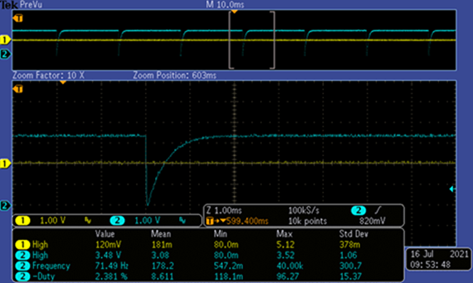
My customer implements one EtherCAT firmware upgrade function, means that F28388D receives software image via EtherCAT and then do flash programming. But after he finish CPU1 upgrade, F28388D fails to boot up and outputs a low signal to XRS pin periodically, please refer to below pictures.

This waveform looks like watchdog reset is happening, but the strange thing is that we don't see 512 OSCCLK(51.2us) low period. My customer cannot connect F28388D via JTAG port with correct password,  then he sets SCI Boot(GPIO72 = 0, GPIO84 = 1), power cycle his system and get same result, F28388D outputs a low signal to XRS pin periodically.

It seems that GPIO72 and GPIO84 cannot force F28388D to do SCI_Boot, I know User OTP can change boot mode GPIO pins, but my customer didn't do that.

Please advise your comments if any, how to do further check and recognize what's wrong with this F28388D?

Thanks and regards,

Luke

  • Hi Luke,

    Do you know what all security configuration fields they have programmed ? 

    This waveform looks like watchdog reset is happening, but the strange thing is that we don't see 512 OSCCLK(51.2us) low period.

    How long it's low in the waveform ? It's not clear from the attached snapshot ? If it's not WD reset then could it be due to bad power supply or some external voltage monitor ? Can you request customer to scope that and check.

    Other thing to try is "Test Connection" via .ccxml (target configuration) file.

    Regards,

    Vivek Singh

  • Hi Luke,

    Any more update on this issue ?

    Regards,

    Vivek Singh

  • Vivek,

    The low period is about 51 us, so this should be the watchdog reset.

    I had a further discussion with my customer, found that there was a logic bug of his software. He executed Fapi_issueProgrammingCommand() and then didn't do while(Fapi_checkFsmForReady() == Fapi_Status_FsmBusy);. This means that the software may do Fapi_issueProgrammingCommand() again when Flash controller is still busy, this is the root cause he fails to program flash memory.

    This problem is fixed when my customer executes while(Fapi_checkFsmForReady() == Fapi_Status_FsmBusy) after Fapi_issueProgrammingCommand() function, he can program flash and DSP boot up from flash without problems now.

    My question is that what will happen when software do Fapi_issueProgrammingCommand() when flash controller is still busy? We are still investigate the reason DSP cannot enter SCI boot via GPIO settings after the 'ERROR' flash programming.

    Please advise your comments, thanks for help.

    Regards,

    Luke

  • HI Luke,

    My question is that what will happen when software do Fapi_issueProgrammingCommand() when flash controller is still busy?

    This is tricky one and operation may be undefined because new command may overwrite the setting for previous operation which is not yet completed. 

    We are still investigate the reason DSP cannot enter SCI boot via GPIO settings after the 'ERROR' flash programming.

    Are you changing the GPIO setting and then issue the reset to device ? If not then CPU will not enter new bootmode.

    Regards,

    Vivek Singh

  • Vivek,

    Yes, my customer changes Boot PIN and then power on system, the NG units cannot boot from SCI, we have no idea what's is happening.

    Eventually, my customer figures out his software bug and fixed this problem, but we still don't know the root cause why the device cannot boot up after 'Error' software upgrade.

    Regards,

    Luke

  • This is strange. Programmed SW should have no impact on SCI boot operation after power-up. I know it's working after correcting the SW but if they want to debug it further then I would suggest to remove the Gel file from target configuration file and then after powering up the board in SCI boot mode, connect CCS and step though BOOTROM code to see what is happening. 

    Regards,

    Vivek Singh