This thread has been locked.

If you have a related question, please click the "Ask a related question" button in the top right corner. The newly created question will be automatically linked to this question.

TMS320F280049C: Relationship between TBPHS and CMPA

Part Number: TMS320F280049C

Dear team:

When using the PWM phase shift function, my customer found that setting TBPHS equal to CMPA would cause the CMPA event to be lost. Details are as follows:

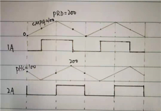
PWM1: UP_DOWN mode, fixed 50% duty cycle, SET for CMPA_U, CLR for CMPA_D, and a synchronization signal when CTR=0;

PWM2: UP_DOWN mode, fixed 50% duty cycle, SET for CMPA_U, CLR for CMPA_D;

PWM2 performs phase shift on the basis of PWM1, and the phase shift value is in the range of 0~PRD. The schematic diagram is as follows:

The problem now is that when the TBPHS value is close to the CMPA value (for example, CMPA=100, PHS=99/100/101), the waveform sent by PWM2 will be lost. The situation is shown in the figure below:

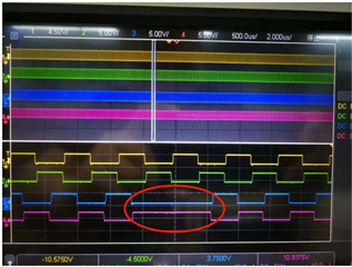
May I ask what causes it? What needs to be done?

  • Hi,


    The problem now is that when the TBPHS value is close to the CMPA value (for example, CMPA=100, PHS=99/100/101), the waveform sent by PWM2 will be lost. The situation is shown in the figure below:

    If CMPA=100 and TBPHS = 99 are you observing that CMPA event is missed? This is not expected. But for CMPA=100 and TBPHS = 101 this is expected behavior. I believe, this would be the case for TBPHS=100 as well.
    Can you confirm CMPA=100 and TBPHS = 99 behavior?

  • Oddly for up/dwn count the TBPRD is 2x CMPA load value, must divide by 2 or CMPA most all PWM modules latch up. The need to double period (x2  TBPRD) is odd since the formula we calculate typical PWM clock ticks (ns) * TBPRD load count for the desired frequency or period. Then we also have to divide CMPA pulse width by 2 or it locks up from input of larger load values. Yet the default is 50mHz for x49c EPWM clock as driverlib.lib text states half SYSCLK speed.

    Why not divide by 2 in the silicon hardware for up/down count mode so the calculator equation makes mathematical sense. Other ARM MCU class used driverlib.lib calls to divide period count, so no body expects EPWM divides the period unless past they hit the brick wall.

    C2000 is much better that the half period (TBPRD 2x) may have EPWM clock speed (not divided) by driverlib.lib calls to set TBPRD frequency period. There is a difference between TBPRD frequency and EPWM pulse width (CMPA/B) that seems to get miss-stated as being the period. Especially when it is not at all the period rather it is the pulse width derived by CMPA/B. Please try to state when it is the period or the pulse width in text, they are not both considered the period.

  • Hi,


    The need to double period (x2  TBPRD) is odd since the formula we calculate typical PWM clock ticks (ns) * TBPRD load count for the desired frequency or period.

    Please refer to TRM chapter "18.4.3 Calculating PWM Period and Frequency" for details on calculating period on up and up-down count modes.

    Why not add divide by 2 into the silicon hardware for up/down count mode so the math by calculator makes mathematical sense. Other ARM MCU class used driverlib.lib calls to divide period count, so no body expects EPWM divides the period unless past they hit the brick wall.

    Waveform generation requirements will be different in up vs up-down count mode. in up-down, one typically generates symmetrical PWM output w.r.t period. Hence, it makes sense have CMPA as half of period.

    C2000 is much better that the half period (TBPRD 2x) may have EPWM clock speed (not divided) by driverlib.lib calls to set TBPRD frequency period.

    What is the default PWM clock you are observing in your hardware? It should be 100MHz.
    Also, check your clock source frequency if you are using an external oscillator and PLL configuration to make sure system is actually running at 100MHz.

  • Hi, 

    What is the default PWM clock you are observing in your hardware? It should be 100MHz.

    Driverlib.lib note states the EPWM clock defaults to half main oscillator speed (50MHz) prior to any pre-scale division, is that a mistake?

    Waveform generation requirements will be different in up vs up-down count mode. in up-down, one typically generates symmetrical PWM output w.r.t period. Hence, it makes sense have CMPA as half of period.

    The point is when doing the frequency math to determine speed F=1/period for any other timer we don't divide period or pulse width by two.

    Keeping consistent logic mandates EPWM up/dwn count mode has built in timer division, especially so mathematical expressions remain constant. CPU is doing period/pulse divisions when the TBPRD CMPA sub modules should Not be offloading silicon functions to the CPU. Seemingly offloading count divisions to the CPU can causes glitches to appear even via shadow loads. I would bet if the up/dwn counter did it's own division via silicon some odd behaviors would disappear not only in C2000 but all PWM modules on earth.  

  • Hi,

    Driverlib.lib note states the EPWM clock defaults to half main oscillator speed (50MHz) prior to any pre-scale division, is that a mistake?

    It really depends on the hardware - the crystal frequency on your board and PLL configuration etc.
    There is no additional clock division for PWM as default.

    Keeping consistent logic mandates EPWM up/dwn count mode has built in timer division, especially so mathematical expressions remain constant.

    Application doesn't switch between up count and up-down count modes. Calculations can be specific to the targeted mode of operation.
    But I see your point, the duty vs. period in terms of the ON/OFF times of PWM is double in up-down count mode. Hence it it has to be accounted for in the CMPA computations.

  • It really depends on the hardware - the crystal frequency on your board and PLL configuration etc.
    There is no additional clock division for PWM as default.

    The thread has F28004x MCU in that context driverlib.lib being included with TI project builds for x49c MCU states EPWM clock defaults to 50mHz. Can you please confirm if that is true?

    //#############################################################################
    //
    // FILE: epwm.h
    //
    // TITLE: C28x EPWM Driver
    //
    //#############################################################################
    // $TI Release: F28004x Support Library v1.07.00.00 $
    // $Release Date: Sun Sep 29 07:29:19 CDT 2019 $
    // $Copyright:
    // Copyright (C) 2019 Texas Instruments Incorporated - http://www.ti.com/

    //*****************************************************************************
    //
    //! Set the time base clock and the high speed time base clock count pre-scaler
    //!
    //! \param base is the base address of the EPWM module.
    //! \param prescaler is the time base count pre scale value.
    //! \param highSpeedPrescaler is the high speed time base count pre scale
    //! value.
    //!
    //! This function sets the pre scaler(divider)value for the time base clock
    //! counter and the high speed time base clock counter.
    //! Valid values for pre-scaler and highSpeedPrescaler are EPWM_CLOCK_DIVIDER_X,
    //! where X is 1,2,4,8,16, 32,64 or 128.
    //! The actual numerical values for these macros represent values 0,1...7.
    //! The equation for the output clock is:
    //! TBCLK = EPWMCLK/(highSpeedPrescaler * pre-scaler)
    //!
    //! \b Note: EPWMCLK is a scaled version of SYSCLK. At reset EPWMCLK is half
    //! SYSCLK.
    //!
    //! \return None.
    //
    //*****************************************************************************
    static inline void
    EPWM_setClockPrescaler(uint32_t base, EPWM_ClockDivider prescaler,
    EPWM_HSClockDivider highSpeedPrescaler)

  • Hi,


    What values are you passing to these two functions in your application?
    EPWM_setClockPrescaler(uint32_t base, EPWM_ClockDivider prescaler,
    EPWM_HSClockDivider highSpeedPrescaler)

    you can compute the EPWM clock frequency based on the explanation provided in the function header.

  • What values are you passing to these two functions in your application?

    Blue note claims SYSCLK speed (our case 100mHz) is not the default rate of EPWM clock at reset and said to be half or (50mHz) well before any pre-scale register entry.

    Seemingly DIVIDER_2 is required for 100mHz EPWM clock is that correct? We assume EPWM clock (blue note) is used for TBPRD module. This exact clock rate is important to calculate the number of ticks of up/dwn count period or frequency. So an arbitrary PWM half period is then a division of the EPWM clock rate and not SYSCLK speed, unless prescale DIVIDER_2 is used to configure EPWM clock?   

    I make this observation period can fool us into believing 20Khz as seen on scope probe. Though CMPA may lock up on certain load values that exceed the arbitrary 1/2 period used in shadow updates of CMPA. Or otherwise CMPA may not produce a full duty cycle range SW directives mandate. 

    // Set 50Mhz PWMCLK, at reset EPWMCLK is half SYSCLK 100Mhz.
    EPWM_setClockPrescaler(obj->pwmHandle[cnt], EPWM_CLOCK_DIVIDER_1,
    EPWM_HSCLOCK_DIVIDER_1);

  • Hi,


    Seemingly DIVIDER_2 is required for 100mHz EPWM clock is that correct?

    No, PWM can work at 100MHz.

    So an arbitrary PWM half period is then a division of the EPWM clock rate and not SYSCLK speed, unless prescale DIVIDER_2 is used to configure EPWM clock?   

    Yes, this could a reason why you maybe observing half clock rate. Choose /1 option.

    // Set 50Mhz PWMCLK, at reset EPWMCLK is half SYSCLK 100Mhz.
    EPWM_setClockPrescaler(obj->pwmHandle[cnt], EPWM_CLOCK_DIVIDER_1,
    EPWM_HSCLOCK_DIVIDER_1);

    These are being set to /1. So, comment seems incorrect.

  • Checked  x49c again, 1/2 period loaded into TBPRD is 2500 ticks. That was based on engineer note 100mHz EPWM clock rate. Technically should be set 1250 ticks for 50mHz clock rate 50% duty. On my other TI PWM module (up/dwn) has 60mHz clock (3000 ticks) and 1/2 period load is set 1500 ticks and prodcues perfect 50% duty 20kHz. 

    Perhaps the TBPRD module has built in divide by 2 for up/dwn count mode after all?

  • And for 100mHz EPWM clock 1/2 period (2500 ticks) should produce 40kHz period. Yet the frequency on scope is 20kHz.  Seemingly the EPWM clock speed is 50mHz or TBPRD module is dividing by 2 the 2500 tick load period for us.