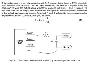
Other Parts Discussed in Thread: LAUNCHXL-F280049C, BOOSTXL-DRV8320RS
I have followed the instruction for laboration 3. But first a picture of my setup just for the record:
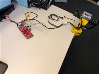
LaunchXL-F280049C, BoostXL-DRV8320RS, Teknic M2310P motor. Supply voltage 36V
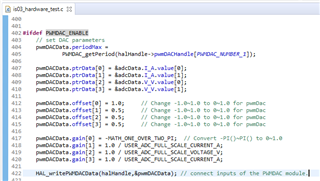
Here I have added the 3a code to connect the inputs of the PWMDAC. (Function call is spelled wrong in the guide!)
First problem, I do not know at what pin's these PWMDAC1-4 signals are generated?
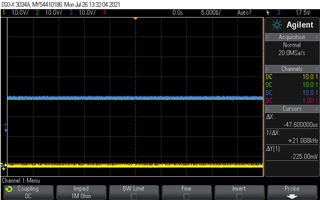
Anyhow I started the code and just Measured the phase voltage signals to see what where going on. When the motor was disconnected from the phases.
Running the code without setting the flagEnableSys, this is what happens. All phases except the yellow (phase A) idle high, as i think de default should..
Phase A = ch1 (yellow), Phase B= Ch2 (Green), Hase C= Ch3 (Blue). I tried to replace the hardware circuit boards to another pair, and the same problem, so the only I have not changed is the code.
What could the issue be causing this? It seem that the phase A control signals is not generated by PWM hardware.. Looked at the gatesignals and the same problem there..