This thread has been locked.

If you have a related question, please click the "Ask a related question" button in the top right corner. The newly created question will be automatically linked to this question.

TMS320F28388D: CCS/TMS320F28388D Build3 Torque Control Example, Current Sine Wave is distorted

Part Number: TMS320F28388D
Other Parts Discussed in Thread: TMS320F28069

Hi Dear.

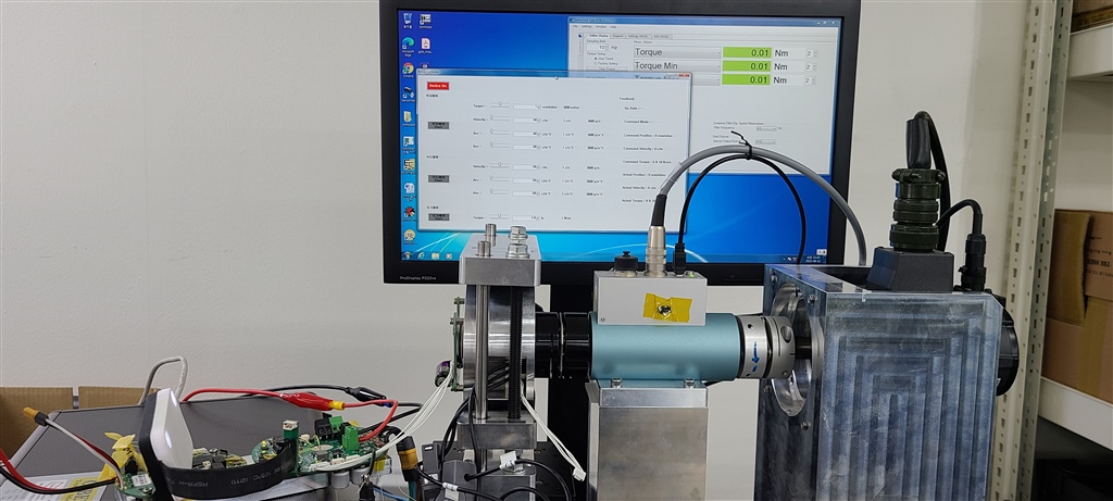
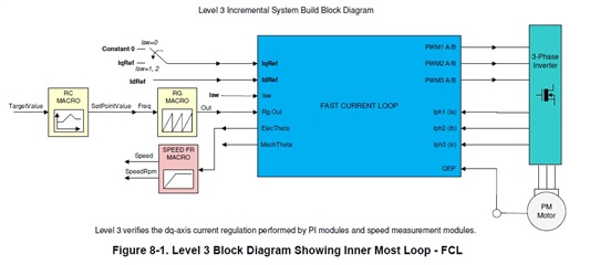
I using the F28388D with application, which is based on the Motor Control Library Build3 Example.

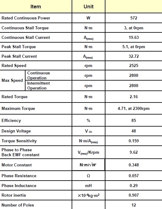
the following is Motor Parameters and configuration

#define CGND HOT //COLD
#define BUILDLEVEL FCL_LEVEL3
#define SAMPLING_METHOD SINGLE_SAMPLING // DOUBLE_SAMPLING //
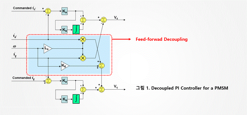
#define FCL_CNTLR PI_CNTLR // CMPLX_CNTLR //
#define CURRENT_SENSE SHUNT_CURRENT_SENSE //SD_CURRENT_SENSE // LEM_CURRENT_SENSE //

#define RS 0.113                                       // Stator resistance (ohm)
#define RR NULL                                      // Rotor resistance (ohm)
#define LS 0.000374                                 // Stator inductance (H)
#define LR NULL                                       // Rotor inductance (H)
#define LM NULL                                       // Magnetizing inductance (H)
#define FLUX 0.962                                   // BEMF constant (V/Hz)
#define POLES 12                                     // Number of poles
#define ENC_SLOTS 65536                      // Numer of slots in the encoder

#define M_ID_START 0.04                         // alignment reference d-axis current, 0.06 -> 8A Injected
#define M_IQ_LI5 0.04                               // reference q-axis current for level5
#define M_IQ_LN5 0.00/*0.04*/                  // ref q-axis current for no level5

//
// Define the base quantites
//
#define BASE_VOLTAGE 38.1                  // 66/sqrt(3) = 38.1 by alex //38.1 //236.14 // Base peak phase voltage (volt), Vdc/sqrt(3)
#define BASE_SHUNT_CURRENT 47.4  // Base peak phase current (amp),
                                                                   // Max. measurable peak curr.
#define Current_Limit 36.0                  //36.0
#define BASE_LEM_CURRENT 12.0 // ----- do -----
#define BASE_TORQUE                     // Base torque (N.m)
#define BASE_FLUX                           // Base flux linkage (volt.sec/rad)
#define BASE_FREQ 250                   // Base electrical frequency (Hz)
                                                             // rpm = 120*Base_freq/poles

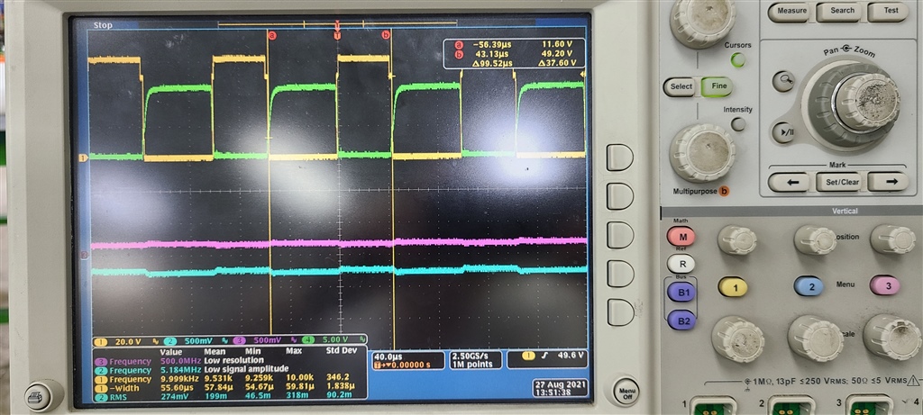
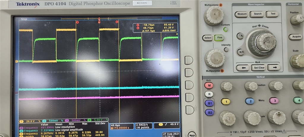
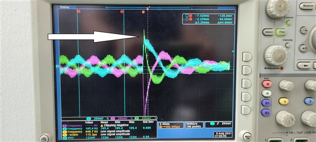
when i run the motor, the torque value under 1A, its operation ok,

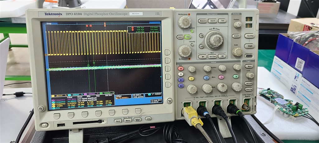
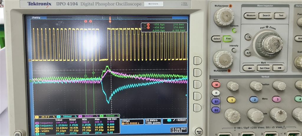
but over 1A, then speed is about 1800 rpm, the Current Sine wave is distort(above picture)

i guess there are some limit conditions, but can't find.

thank you

  • Build level 3 is torque loop and you cannot perform this test without any load on the motor. IF you tried to increase the current reference, then it will attempt to raise it but then without load, it will reach full speed and the inner loop will saturate. 

  • Thank you Ramesh.

    I already use TMS320F28069 with Motor Drive, it is no problem. good.

    but it's old and low performance device, so we move to F28388D Drive.

    (Both board inverter circuits are the same (DRV8323RS)

    As your advice, I Re-test with Motor Dynamo Test Device

    The Below Picture is that,

    Figure 1.

    - Test Environment

    Figure 2. 

    - Test Motor is torque  control based on F28388D Drive and Opposite  Motor(Dynamo Motor) is Speed Control

    -  Test Motor's torque is 0 Amp and Dynamo Motor is running 1,900 RPM, the operation OK.

    Figure 3.

    - Test Motor's Torque is 1.1A and Dynamo Motor is running 1,900 RPM, The operation is abnormal.

      that is, Top FET Gate Signal is missed on 2 cycle, when 3 Phase Current Signal is bounced abnormally

      I guess that the bemf will affect. 

    ( I test same environment, only change motor drive based on TMS320F20869 DSP, it's operation is ok)

    Figure 4. 

    - Test Motor's Torque is 37 A (Motor Max Current), and Dynamo Motor is running 950 RPM, the operation is ok

    but over the 950 RPM, the abnormal state is occurred.

    Figure 5.

    - The motor's Spec

    In the low speed rpm, the Motor is normally operation, but in the high speed rpm test is not normal.

    is it related with bemf?

    Please give me your advice

    Thanks you

    < Figure 1. Motor Test Environment with Motor Dynamo Device>

    Dynamo Motor is panasonic servo Motor

    <Figure 2. Injection Torque 0 A, with Dynamo Motor running RPM 1900>

    Oscilloscope channel Description

    - Ch1 : U-Phase Top FET GATE Signal

    - CH2 : U-Phase Current (scale = 0.1V/A)

    - CH3 : V-Phase Current (scale = 0.1V/A)

    - CH4 : W-Phase Current (scale = 0.1V/A)

    <Figure 3. Injection Torque 1.1A, with Dynamo Motor running RPM 1900>

    <Figure  4. Injection Torque 37A, with Dynamo Motor running RPM 950>

    < Figure 5. Test Motor Spec >

  • Check if over current protection is kicking in to mess up the pulse.

    Secondly, with FCL, there is a limit on max duty cycle that you can use. It basically limits the max speed of operation. If you increase the DC bus voltage, and you are able to run to the same high speed without any problem, it means that you are running into dutycycle limit of FCL. You may have to add some additional code to address this issue. Find out the value of D and Q voltage inputs to PWM generator at the time of this event.

  • Hi, Ramesh

    Thank you for reply

    As your advice. i test.

    first. over current protection is not kicking, when the issue is occurred.

    second. i change the DC bus Voltage 48V -> 55V(as soon as possible), then the issue is occurred from 2100 rpm to 2350 rpm on torque 0 Amp.

    above picture is tested on torque 1.1A and 1900 rpm

    if torque 0A, then the issue is occurred on 2100rpm .

    so i test torque 0A, DC bus voltage 48V, 55V

    48 V : 2100rpm  <- the issue is occurred.

    55 V : 2350rpm <- occurred.

    depends on DC bus voltage, the rpm is moved from 2100 to 2350 rpm.

    and i test anther environment.

    all of the above test is done on PWM Freq 10KHz.

    PWM Frequency Change

    PWM : 10KHz -> 5KHz  (ISR Freq also 5KHz)

    DC Voltage : 48V

    Torque : 0 A

    the issue is not occurred on 2800 rpm (Max Motor RPM)

    would tell me what is the duty cycle limit of FCL, which you said above.

    is it means that the PWM duty cycle or another?

    and if i can modify the duty cycle limit of FCL?


    at last. " some additional code"  is where part. ? 

    thanks

  • A certain amount of computation time is needed to calculate the new values of duty cycle of A, B and C, and this time is lost for new PWM cycle, and hence reduced max duty cycle. When you go lower in PWM frequency, you get a higher dutycycle as the percentage of lost time is smaller in a lower frequency PWM. Conversely, if you increase the pwm frequency, you lose more dutycycle.

    Additional code - you may try to play around with the max values of Vd or Vq - both controller outputs and net compensated max Vd, Vq. See if this helps. To do this, just watch the value of these parameters in the debug window. Whichever is hitting the limit first, try to increase the limit of this one. Just make sure that the vector sum of Vd and Vq is not more than a limit (say 95% or lower). 

  • in the above.

    Is the limit, which you said, means the sum of max Vd and Vq value ?

    if then, how do i decide and increase the limit value ?

    thanks.

  • means the sqrt(vd*vd + vq*vq)

    Different motors can have different values of Vdmax and vqmax. To start with i suggest to test it out in the debug window for your motor under test.

  • I attached the figure 8-1, which is in the Quick Response Control of PMSM Using Fast Current Loop.pdf

    I can't the Vd and Vq Variable in the source code of the fcl_cpu_code.c.

    but the pi_id.out, pi_iq.out is there

    what variable should I check?

    Thanks Ramesh.

  • pi_id.Max/Min and pi_iq.Max/Min

  • Hi Ramesh.

    i test the pi_id.Max/Min and pi_iq.Max/Min with change the limit value up/down

    but the issue is not resolved.

    so i tried to another test

    that is change the TBPRD, which is one of the EPWM Regs.

    when the issue is occured with motor rpm 2100, TBPRD Value is 0x1388( 5000 decmal), 

    the follow figure is the TBPRD 0x1388 Scope screen, Tpwm : 99.52us 

    #define PWM_FREQUENCY           10   // in KHz

    and change the TBPRD Value 0x1500(5376 decimal)

    the follow figure is the TBPRD 0x1500 Scorp screen, Tpwm : 107.5us

    #define PWM_FREQUENCY           10   // in KHz ( the define value is same above)

    in this case FCL Torque mode is operation normaly, when MOTOR RPM 2400.

    is it correct?

    finally. i find the follow figure 

    i wonder that FCL Library is include the Feed-forward Decoupling function?

    tthanks.

  • I think the voltage limits are being reached. When you increase the time period, you get a little more time before maxing out on modulation index and due to this incremental jump in modulation index, you are able to get higher speed. If you reduce the frequency further, you may get further higher speed. Well, see what is the max speed you can get without FCL. That can give some clue as to where things are missing.

    Btw, the library takes care of decoupling voltages as well.

  • Thanks Ramesh.

    I  need to more test about the Max speed without FCL.

    The without FCL Test means Example Build 1 or 2 ?

    and would you tell me where the decoupling algorithm source in the library.

  • comment out FCL_initPWM() in main() and repeat the tests to find out max speed.

    Pls step through the code to understand the details. You may need to spend some time to understand the code organization and logistics. That will help you answer many queries on your own.