This thread has been locked.

If you have a related question, please click the "Ask a related question" button in the top right corner. The newly created question will be automatically linked to this question.

TMS320F280049: F280049 SDFM error handling

Part Number: TMS320F280049
Other Parts Discussed in Thread: C2000WARE

Hi Manoj,

Sorry to bother you again.

I have written the code in a different way, the program can read SDFM filter1 correctly,

but if I try to handle error (Modulator failure), the program keeps entering error handling ISR

PS_SdfmErrorIntr. The only different is to call the following function in a different way.

#if (1)
    PS_SdfmSetErrVec(0, _Sd1Flt1ErrProc);
#else
    PS_SdfmSetErrVec(0, NULL);
#endif

The above function call sets Sdfm1Regs.SDCPARM1.bit.MFIE to 1, and the another one

sets Sdfm1Regs.SDCPARM1.bit.MFIE to 0.

Do I have anything wrong in the code?

thanks,

Jiakai

PS: I have uploaded the project for you review. You need to set 2 include paths as below before compiling it.

${COM_TI_C2000WARE_SOFTWARE_PACKAGE_INSTALL_DIR}/device_support/f28004x/common/include

${COM_TI_C2000WARE_SOFTWARE_PACKAGE_INSTALL_DIR}/device_support/f28004x/headers/include

SdfmDacOnly (C code).zip

  • Jiakai,

    Modulator clock failure (MFIE error) means that SDFM has stopped receiving SD-Cx. Is PWM1 clocking the SDFM? If so, does PWM1 still providing clock to SDFM when you see this problem?

    In PWM, does emulation stop (breakpoint) the PWM. That may be the reason for MFIE error.

    Regards,

    Manoj

  • Your previous post as seems to talk about similar failure. The main thing you need to understand is why did PWM1 stop clocking the SDFM. Please probe PWM1 and check PWM1 configuration.

  • Hi Manoj,

    Thank you for your prompt reply.

    You are right, PWM1 doesn't output 10MHz waveform, but the issue is: when I set Sdfm1Regs.SDCPARM1.bit.MFIE to 1,

    there is no output for PWM1, when I set Sdfm1Regs.SDCPARM1.bit.MFIE to 0, PWM1 outputs 10MHz waveform.

    What causes this? I didn't make any difference on program besides calling PS_SdfmSetErrVec in different parameter.

    thanks

    Jiakai

  • Hi Manoj,

    I have found the wrong place in the previous project:

    1. The global interrupt flag has been enabled(EINT) before initializing SDFM, so when calling PS_SdfmEnable() to

        enable SDFM, SDFM will immediately enter ISR frequently and no progress in the current sequence, so PWM1

        clock cannot start at all because CPU doesn't call PS_PwmStartStopClock(1).

    2. PS_SdfmEnable() should be called after calling PS_PwmStartStopClock(1), and it's better to put a 10us delay in between.

        In this way we can avoid the first modulator failure.

    Thanks,

    Jiakai

  • Hi Manoj,

    About SDFM comparator, I made a project that uses HLTZ as capture input signal, the capture gets the counter at the rising edge.

    Since SDFM's input signal is an 1Hz triangular waveform, capture counter got should be around 100,000,000, that is 1 second.

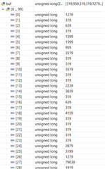
    But when I run the program, I got the following capture counter values:

    the minimum counter value is 319 (3.19us). the maximum value is 39678(396.79us).

    Do I have anything wrong in the code?

    thanks,

    Jiakai

    PS: My project is attached as follows:

    SdfmDacOnly (C code) (2).zip

  • I'm glad to know that MFIE issue got fixed. Did you make sure to check ECAP module is working as expected? Did you try plugging a clock signal to ECAP and make sure ECAP is providing the correct frequency?

  • Hi Manoj,

    No yet, I have described the issue 6 hours ago at another thread of this post.

    Thanks

    Jiakai

  • Please try the suggestion I mentioned in previous post before you proceed with checking the frequency of SDFM comprator events. I don't see how this can be debugged without making ECAP configuration is correct.

  • Hi Manoj,

    This project can get the correct SDFM value, and SDFM interrupt and eCap interrupt work fine.

    So I think there is no hardware issue. The only issue is the program enters eCap interrupt more frequently.

    Could you check the code to find any wrong places?

    By the way, do you have any examples that uses SDFM comparator?

    thanks,

    Jiakai

  • Jiakai,

    I didn't say it is a hardware issue. It would be a software issue. It is very difficult for me to look into your code snippets to understand what you are trying to do. Also your code isn't based on driverlib (or) bitfield. It looks like you have comeup with your own method to code the device.

    We don't a example code which measure the frequency of SDFM comparator events using ECAP.

    Regards,,

    Manoj

  • Hi Manoj,

    I will change TI's SDFM ex5 example to implement the same functionalities.

    thanks,

    Jiakai

  • Did you already try to make sure ECAP is correctly detecting frequency for valid clock signal? I have already made this suggestion in my previous thread. This would be the easiest way to debug this problem

    Regards,

    Manoj

  • Hi Manoj,

    I have found the program is OK. Since I use DAC to generate an 1Hz triangular 0 to 0.25V waveform as SDFM input, and set 0.15V as zero crossing threshold voltage, DAC will output 0.15V to SDFM and it makes SDFM comparator COMPZ signal unstable. Perhaps TI should set comparator output hysteresis to avoid it. SDFM comparator's COMPZ output becomes ok if I change triangular waveform from 1Hz 50 50Hz.

    By the way, when I changed code to the drivelib style, I found that there are no COMPZ signal definitions in ECAP_InputCaptureSignals.

    Thanks,

    Jiakai