This thread has been locked.

If you have a related question, please click the "Ask a related question" button in the top right corner. The newly created question will be automatically linked to this question.

TIDM-02007: TIDM-02007:motor start up problem

Part Number: TIDM-02007

Hi Team,

I am currently using TIDM-02007 for testing. The code I tested is Level4.

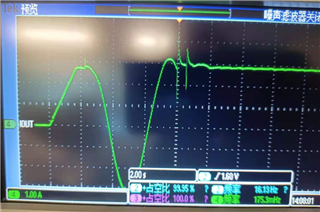
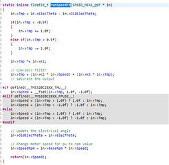
During the start-up process, the motor will shake.This seems to be caused during the process from "ENC_ALIGNMENT" to "ENC_WAIT_FOR_INDEX"

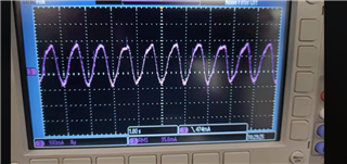
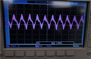
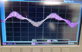
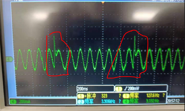
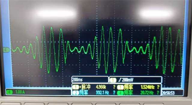
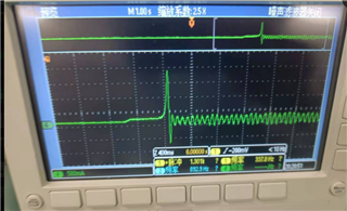
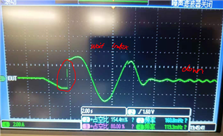
As shown in the figure, when the current has a sudden change, the motor will vibrate.

May I ask what causes this? Should we improve this situation?Is it the impact of not setting the parameters?

Thanks

Jenson

  • Was LEVEL3 testing ok?  IF you saw the same problem, then you may have to swap two wires to the motor.

    If LEVEL3 is ok, then the problem may be high values of speed loop PI gains. You may reduce that. Also, you may want to reduce teh start up IqRef value. Pls review the code in LEVEL4 at the starting sequence to figure this out.

  • Hi Ramesh,

    Now, I'm using LEVEL3 and that's the same thing. When I swap the two motor wires, I see that the motor does not spin properly, like a stall.

    This occurs after the Index is received,and why is this happening?

    It would be nice to swap the motor wires back, but there would still be a startup vibration.

    I want to know why a stall occurs after the wire is swapped and I should improve the startup vibration.(modify Speedloop PI?)

    Thanks

    Jenson

  • If the sense of rotation of ABC sequence in the motor and that of the encoder feedback are opposite, then the motor will stall. That is the reason for swap. If the original sequence was ok in BUILD3, then that sequence is correct.

    If you get good LEVEL3 performance in starting, then in LEVEL4, set the starting IqRef value to be around what you used in LEVEL3 and go from there.

  • Hi Ramesh,

    In Level3, the motor will start to vibrate.In Level3, the motor will start to vibrate. Do I need to modify the Iqref?Or is there anything else that needs attention?

    Thanks

    Jenson

  • Are you using a different motor than what was referenced in the guide? If you are running without load, then you dont need a higher Iqref, you may reduce it and see if it is getting better. 

  • Hi,

    Yes, I am using my own motor and I will try your suggestions. And then update to you 

    Thanks

    Jenson

  • Hi Ramesh,

    Thanks for your help,This is useful.

    But currently I have encountered a new problem,Under the same speed loop KP and Ki, the forward rotation and reverse rotation of the motor behave differently.

    Forward current waveform:

    Reverse current waveform:

    I think this is wrong. There should be no difference between forward rotation and reverse rotation. Do you have any comments on this?

    Thanks!

    Jenson

  • I would suspect the deviation of angle feedback zero degree with actual zero degree of phase A that is the basis angle for FOC. Try to tweak this value and see if it helps.

  • Hi Ramesh,

    Do you mean you want me to modify IdRef_start or alignCnt to get a more accurate initial positioning of the motor?

    Thanks.

    Jenson

  • You could try that. Or, within the debug window, play around with the value of calibratedAngle. Try tweaking values basically to see where the potential fix could be.

    If it does not get better, I would think that the non linearities (or errors) in feedback sensing of phase current could be the reason. The control is based on angle and currents. If angle is not contributing to error, then it can be the currents only. See if the phase current sensing is alright. 

    First, you may run the motor in open loop in both directions and confirm if direction is not an issue reg current wave shape.

  • Hi Ramesh,

    Thank you for your help. I am currently using our reference design to drive the customer's new motor. Currently Level2 can work normally. But when I was in Level 3, I found a strange phenomenon.

    1. The iq_fbk of the motor can follow iq_ref. When I set iq_ref to 0.01, iq_fbk can follow iq_ref very well. But there will be abrupt changes in the current waveform. And the torque of the motor is very small. When I load the motor, the motor stops.

    2. When I set iq to 0.1, iq_fbk can follow iq_ref, but the following fluctuations will be large, and the current of the motor is also very strange. It seems that there is a problem with the PI parameter setting of the current loop.

    It seems that there is something wrong with the adjustment of the current loop. Do you have any comments on this?

    Thanks

    Jenson

  • The abrupt spike is something to do with feedback sensing. It could be noise pick up in sensed current value or it could be in position feedback. From the location of spikes in the current waveform, it appears that this problem could be sourced from position feedback. Consider checking the position feedback.

    Secondly, if level 3, the motor operates in constant current (constant torque) mode. In this mode, if you apply a load greater than what you are commanding, then the motor will stop, which is natural.

  • Hi Ramesh,

    How should I check the location feedback?
    In the level, I can observe normal speed feedback follow. But the current is abnormal at level3. For the ADC, my settings have not changed. In theory, it should not be the effect of current sampling. Does this have anything to do with the parameter settings of the motor? But my level2 display speed feedback is normal

    Thanks.

    Jenson

  • Jenson,

    Given the problem statement, I can point out the potential problem areas for you look at and debug. I dont know what else to suggest. It appears like there is a glitch in the position feedback. Monitor the position waveform instead of speed. Speed derivation may have a filter to smooth out any glitches.

  • Hi Ramesh,

    I checked the  encoder lines of the motor, because the customer provided the wrong number of encoder lines, so there will be this fault.Thanks for your help.

    In addition, I have some questions:

    1.When the motor is in the state of “wait for index”, the rotation of the motor is not so smooth. Although the current waveform is ok, it will have an effect similar to that of a stepper motor. I don't know that why. And we would like to let the motor enter speed loop.Is there any way to make the motor fast and smoothly complete the "wait for index' process?

    2.During the process from wait for index to CALIBRATION_DONE, the motor has a certain probability of losing control. The motor speed will reach the maximum speed and is not controlled.

    But this is only an occasional phenomenon, why is this? Do you have any comments on this?

    Thanks

    Jenson

  • Hi Ramesh,

    1.I tested our system again, in order to make the motor drive more smoothly during the wait for index process. I will be Iq=pid_spd.term.Out in this process. From the results of the test, it seems that there has been improvement. I want to know what are the hidden dangers of my changes like this? Why should iq_refer be used initially?

    2.During the test, there is still a small probability that the motor is out of control. Its performance is that when the wait for index phase is switched to done, the motor current will suddenly change, and then the speed of the motor will reach the maximum value and cannot be controlled.The current change will increase abruptly, and then the motor will reach the maximum speed in the forward/reverse direction. May I ask what causes this? What kind of comments do you have on this?

    Thanks

    Jenson

  • When the motor is in the state of “wait for index”, the rotation of the motor is not so smooth. Although the current waveform is ok, it will have an effect similar to that of a stepper motor. I don't know that why. And we would like to let the motor enter speed loop.Is there any way to make the motor fast and smoothly complete the "wait for index' process?

    You can reduce the align current or IqRef to smoothen it up. The original intent was to take care of any load that may be tied to the motor shaft that may be opposing the rotation.

    During the process from wait for index to CALIBRATION_DONE, the motor has a certain probability of losing control. The motor speed will reach the maximum speed and is not controlled.

    Well, dont have an answer, you may have to debug it

    I tested our system again, in order to make the motor drive more smoothly during the wait for index process. I will be Iq=pid_spd.term.Out in this process. From the results of the test, it seems that there has been improvement. I want to know what are the hidden dangers of my changes like this? Why should iq_refer be used initially?

    yes, there are many ways of doing it, suggest to come up with what you like. Ours is just an illustration.

    During the test, there is still a small probability that the motor is out of control. Its performance is that when the wait for index phase is switched to done, the motor current will suddenly change, and then the speed of the motor will reach the maximum value and cannot be controlled.The current change will increase abruptly, and then the motor will reach the maximum speed in the forward/reverse direction. May I ask what causes this? What kind of comments do you have on this?

    You may have to work through this transition to see what parameters are missing out. Difficult to to throw a specific suggestion without physically debugging the issue.

  • Hi Ramesh,

    Thanks for your kindly help.

    I did an experiment today to test the cause of the motor out-of-control event.

    First of all, from the current waveform, in the process from wait for index to Done, there will be a sudden change in current, and then the motor will run at the fastest speed. Not under the control of the speed loop. I found that the possible cause of the sudden change in the current is the sudden change in the speed feedback. So I want to know how the electrical angle is calculated to get the speed, and how is the low-pass filter designed?

    Another problem is that when switching from wait for index to done, fclVars[0].pangle switches from fclVars[0].rg.Out; to fclVars[0].qep.ElecTheta. Will this produce system shocks?

    In addition, for the stage of Wait for index, if the value of Iq_ref is too small when setting Iq_ref, the motor cannot be rotated. If the motor can be rotated, the rotation will not be smooth at this stage. What is the solution to this problem?

    (Current waveform when the motor is out of control)

    Thanks for your help again!

    Jenson

  • Speed is calculated as the difference in angular position and is passed through an LPF.  If you see speed jitters, then the input position fed into speed calc is the one i would suspect and not the speed calc routine itself. 

    Another problem is that when switching from wait for index to done, fclVars[0].pangle switches from fclVars[0].rg.Out; to fclVars[0].qep.ElecTheta. Will this produce system shocks?

    ideally they should start with the same value, if there is a drastic difference in value, it can lead to this problem.

    Reg IqRef, you will have to find what suits your app by trial and error I guess.

  • Hi Ramesh,

    Thanks very much for your help.

    For the calculation of speed, I want to know how the K1, K2, and K3 coefficients are defined? Are there any instructions for use?

    The result of today's test is that changing the value of Id_ref will improve the motor out of control event. So I am wondering whether it is related to the value of calibratedAngle. So I want to know which value in the program indicates the value of calibratedAngle? How to ensure that the motors are in alignment?

    Thanks!

    Jenson

  • I dont have reference material for K1, K2, K3. It sets up a low pass filter. If you suspect that, you can custom design it and use. I dont think this LPF is an issue for your situation.

    The value counted in the QEP POSCNT register at the instant of getting index pulse is what sets up the calibrated angle. For your other queries, I guess you may have to perform experiments at your side as we are out of remote suggestions.

  • Hi Ramesh,

    Thanks for you help!

    At present, customers have doubts about our calibration, because every time the power is turned off, the motor will be calibrated. Do we necessarily need to calibrate? Or do we have any plan to reduce this process?

    If the customer wants to make the acceleration and deceleration faster, can I choose to modify the RC coefficient, is there any other method?

    Thanks again.

    Jenson

  • Since our demo is to show how to arrive at calibrated angle, we identify it every time it is run. Instead, one could run the calibration many times and find out what is the value of mean calibrated angle. This value could be hardcoded as calibrated angle. This way there is no need to run calibration every time.

    Yes, RC coefficient is the way to go if you use TI code. Some users implement an LPF on the speed command, and set up the filter coefficient to the ramp rate needed. I would think TI method is better.

  • Hi Ramesh,

    Thanks for your help.

    If I find the calibration value obtained by taking multiple experiments, how should I assign the value to the calibration angle?

    Is it directly assigned to QEP POSCNT, I think it might not be right?

    Thanks again.

    Jenson

  • You can bypass the calibration step and assign this value directly to CalibratedAngle at declaration itself.

  • Hi Ramesh,

    Thanks for your Patient help!

    1. For the calibration process, my understanding is to write QPOSCNT as a fixed value at the current position? Is this understanding correct? If you mean this, I want to know, because the position of the motor is uncertain every time, can a fixed calibration value be used for processing? (I have performed an experiment and assigned the value of QPOSCNT, but it will jitter at startup, but it can work normally after jitter. But is there a way to avoid jitter? If you do not start at this position next time, it may not start with the same QPOSCNT, right?)

    2. For the output current of the current loop. I found that if the motor is stalled, the current in my motor will reach a fixed value, and then it will not increase (this value is less than the value of M1_MAXIMUM_CURRENT and currentLimit I set). At the same time, I checked the iq loop of the current and found iq The output of Umax is no problem at this time, but iq_FB is always a smaller value. Why at this time? Are there any factors that limit the current output? (My motor's locked-rotor current can reach up to 7A, and the current can only reach 3A when it is tested at 18V locked-rotor)

    3.For Level3, it can work normally, but I found that when the value of iq is 0.005~0.006, the speed corresponds to 0~50RPM, and above 0.007 is 60RPM (the speed corresponding to the maximum electrical frequency I set). I want to know what is the correspondence of this value? Since the corresponding iq is very small, I am wondering if there is any way I can zoom in, so I can test it easily

    Thanks

    Jenson

  • 1. Basically you write the calibrated angle into POSINIT register. Pls follow the code sequence to understand how to go about this.

    2. I dont have an answer for this, you may have to debug more on this

    3. With no load on the motor shaft, a small Iq will run the motor to full speed. At Iq of 0.05, one could easily hold the motor shaft and stop it.

  • Hi Ramesh,

    Thanks for your help.

    I currently manually write POSINIT, and then directly start it in CALIBRATION_DONE, and then found that it is indeed possible to go without calibration. This is beyond the scope of my understanding, because if it is calibrated, POSINIT is very random, but when manually assigning values, only specific values can be started normally. Why is this? What kind of work does our calibration do? Why does incorrect POSINIT make the motor unable to work normally? I need to explain this question carefully to the customer, so could you kindly help me understand, thank you?

    Jenson

  • The intent of calibration is to identify the offset count between electrical angle ZERO of stator phase A and the index pulse of QEP. At index pulse, the counter can be reset to start from ZERO again, OR, the counter can be reset to ZERO when POSCNT >POSMAX.

    Option 1:- If the index pulse is used to reset POSCNT to ZERO, we have to add the offset angle to get the electrical angle.

    Option 2:- If index pulse is not used to reset POSCNT, and that POSMAX is used to reset, then during every index pulse, reload the value of POSINIT into POSCNT and start counting from this value. POSCNT ZERO will occur when the POSCNT value exceeds POSMAX. 

    Pls review the code and you should be able to figure out the logic.

  • Hi Ramesh,

    Thank you very much for your patient answers!

    I will experiment again and read the RTM of C2000, if there are follow-up questions, I will ask you.

    But at the moment I have another problem, which is that the current loop of the motor cannot reach the value I want. At level 3, I locked the motor, and iq_fbk could not reach the maximum value of the iq loop. I have checked many places to see if there are programs that restrict it, but there are no results. The level3 code I used is the original code without modification (the motor parameters have been configured), iq_fbk can follow iq_fbk when the value is small, but when iq_ref is large, iq_fbk cannot follow it to reach a larger value ( When the motor voltage is increased, iq_fbk will also increase, which is closer to iq_ref), I did not find what caused this problem. Can you provide any suggestions?

    In addition, I would like to ask about the difference between M1_MAXIMUM_CURRENT and motorVars[0].currentLimit. I check the code M1_MAXIMUM_CURRENT does not seem to limit the current of the motor, is it only related to the calculation of the motor current by the ADC?

    Thanks again.

    Jenson

  • If you dont load the motor, IqFbk cannot go to higher values. Try this test while loading the motor somehow. You will have to figure out how to load the motor

    MAx current is limited by what the motor can draw for the given load on the shaft. Software is not limiting it to lower value.

  • Hi Ramesh,

    In fact, I increased the load. I made the motor fixed and will not rotate, simulating the current when the motor is locked.

    In fact, I increased the load. I made the motor fixed and will not rotate, simulating the current when the motor is stalled. According to the ideal situation, when the motor is stalled, the Iq value should reach the maximum, and iq_fbk will also reach the maximum (within the maximum locked-rotor current of the motor), but At present iq_fbk has not reached a very large value, it will increase only when the motor voltage is increased, which makes me very confused.Do you know what could be causing this?

    Thanks a lot!

    Jenson

  • You need enough voltage to pass the required current. The PI controller will adjust its output such that enough voltage is applied on the motor, If the input voltage is lesser than what is needed to pass maximum current (I=V/R), then the current will also be lesser.

  • Hi Ramesh,

    Yes, you are correct, but I have tested that the maximum current of the motor can reach 7A at 18V (using the power supply in the UV phase), but during the system test, I stalled the motor and it can only reach 3A.I think this may not be the reason for the insufficient voltage, what do you think?

    Thanks

    Jenson

  • Sorry, I am out of suggestions at this point. You may have to spend some more time debugging.

  • Hi Ramesh,

    At present, the customer requests to send them the current value, and I get the current value from the ADC. I use the following code to get the current value.

    motorVars[0].currentAs = HWREGH(motorVars[0].curA_PPBRESULT) * motorVars[0].currentScale;

    motorVars[0].currentBs = HWREGH(motorVars[0].curB_PPBRESULT) * motorVars[0].currentScale;

    motorVars[0].currentCs = HWREGH(motorVars[0].curC_PPBRESULT) * motorVars[0].currentScale;

    The ADC value is currently available, but sometimes the ADC value is very strange, 

    Sometimes the ADC figure is correct, sometimes it is 527.9. This makes me wonder, is motorVars[0].curA_PPBRESULT data overflow? How should I modify it? Do you have any advice?

    Thanks.

    Jenson

  • Hi Ramesh,

    I checked out that this is a data format problem, and it is currently resolved, thank you!

    Jenson

  • Hi Ramesh,

    1.What I check is the current pid parameter setting of the current loop (iq) as shown below. Is there any theoretical basis for this setting? Are there any reference settings? Secondly, how to roughly debug the setting of the speed loop?

    2.What is the relationship between Iq_out and Iq_fbk and the current value? For example, if I set Iq=0.5 in Level, what is the corresponding output current of the motor? Is he related to M1_BASE_CURRENT? What is their relationship. (Currently, customers use level3 and want to know what is the output current corresponding to the input iq)

    3.In wait for index, it is necessary to call this RC MACRO. What is the function of this module? Why do we need this module?

    Thanks.

    Jenson

  • Jenson,

    I think this thread is now going all around with many issues. Can you close the thread and start a new thread for a different query from now on? I can answer this particular query here though.

    1.refer to this link

    (+) Teaching Your PI Controller to Behave (Part I) - Industrial - Technical articles - TI E2E support forums

    2. Per unit scale normalizes the variable on a scale of 1.0, and the base value is the max value the hardware sensing circuit can sense.

    3. Pls read the user guide for what this function does.

  • Hi Ramesh,

    Sure,I will reopen a new thread if there are other problems.Thanks very mcuh.But at the moment I still have questions about this problem

    2.Per unit scale normalizes the variable on a scale of 1.0, and the base value is the max value the hardware sensing circuit can sense.

    Yes, I agree with your point of view. But I want to confirm that max value the hardware sensing circuit can sense in this program refers to M1_BASE_CURRENT instead of M1_MAXIMUM_CURRENT, right?

    3. Pls read the user guide for what this function does.

    I have checked the comments of the code, which says it is RAMP (Sawtooh) Generator Macro Definition. But so I think this may be the ramp up of the angle in the open loop state at startup. Is this correct?

    Thanks 

    Jenson

  • 2. yes

    3. RC macro controls the ramp rate of speed ref setting. RG macro does ramp control at startup.

  • Thanks for your kindly help Ramesh!

    Jenson