This thread has been locked.

If you have a related question, please click the "Ask a related question" button in the top right corner. The newly created question will be automatically linked to this question.

LAUNCHXL-F280049C: Default Interrupt handler & TM1, TM2

Guru 56218 points

Part Number: LAUNCHXL-F280049C
Other Parts Discussed in Thread: C2000WARE

Hello

It seems C2000 default interrupt handler (Interrupt.h) fails to remove CPU timers 1 and 2 when ever they are registered by the application. Otherwise CPU timers may be enabled IE but there is no vectoring of application to either one. Yet when Timer 0 is enabled as PIE interrupt interferes with Group 1 channel interrupts timing on clear ACK Group 1 from either registered vector different interrupt source. How to fix this issue or was there an update to interrupt.h to fix this issue?

The TI project does not have a vector table but uses CPU Timer 0 for another experiment not in this application. Enabling unused timer 0 I discovered it interferes with another registered interrupt handler in Group1, the reason to use CPU timer 2 for 100ms reloads. Note CPU Timer1 and Timer TRB register is never togged 1 via register continuous refresh.

//*****************************************************************************
//
//! \internal
//! The default interrupt handler.
//!
//! This is the default interrupt handler.  The Interrupt_initVectorTable()
//! function sets all vectors to this function.  Also, when an interrupt is
//! unregistered using the Interrupt_unregister() function, this handler takes
//! its place.  This should never be called during normal operation.
//!
//! The ESTOP0 statement is for debug purposes only. Remove and replace with an
//! appropriate error handling routine for your program.
//!
//! \return None.
//
//*****************************************************************************
static void Interrupt_defaultHandler(void)
{
    uint16_t pieVect;
    uint16_t vectID;

    //
    // Calculate the vector ID. If the vector is in the lower PIE, it's the
    // offset of the vector that was fetched (bits 7:1 of PIECTRL.PIEVECT)
    // divided by two.
    //
    pieVect = HWREGH(PIECTRL_BASE + PIE_O_CTRL);
    vectID = (pieVect & 0xFEU) >> 1U;

    //
    // If the vector is in the upper PIE, the vector ID is 128 or higher.
    //
    if(pieVect >= 0x0E00U)
    {
        vectID += 128U;
    }

    //
    // Something has gone wrong. An interrupt without a proper registered
    // handler function has occurred. To help you debug the issue, local
    // variable vectID contains the vector ID of the interrupt that occurred.
    //
    ESTOP0;
    for(;;)
    {
        ;
    }
}

  • To help assist TRM explicitly states CPU Timer1 and Timer2 do not require to enable IER or to assert clear ACK in the handler. 

  • Hi,

    I am not sure I understood your question correctly. In an application, when an interrupt is enabled, it is required to register an ISR for it. By default, we fill the address of Interrupt_defaultHandler as a fallback address in case application fails to register it.

    Yet when Timer 0 is enabled as PIE interrupt interferes with Group 1 channel interrupts timing on clear ACK Group 1 from either registered vector different interrupt source. How to fix this issue or was there an update to interrupt.h to fix this issue?

    Enabling unused timer 0 I discovered it interferes with another registered interrupt handler in Group

    I did not understand this statement. Can you explain what the issue is?

    To help assist TRM explicitly states CPU Timer1 and Timer2 do not require to enable IER or to assert clear ACK in the handler.

    That's right. Timer1 and Timer2 are directly connected to C28x interrupt line and are not connected via PIE. Hence ACKing is not required. Are you seeing this being done in any example code from C2000ware?

    Regards,

    Veena

  • Please take a look at the driverlib example on cputimers where interrupts are enabled for all the 3 timers. We register different ISRs for these interrupts and PIE group is ACKed in case of Timer0 interrupt.

    <C2000Ware>\driverlib\f28004x\examples\timer

    Regards,

    Veena

  • Hi Veena,

    Please take a look at the driverlib example on cputimers

    Already confirmed imported project into CCS and CPU TM1, TM2 interrupts are not asserting using the driverlib calls. Only ePIE TM0 interrupt Group1 INT7 is functional and the application used TM1 as SW 1ms tick event so it can't be used either and ADCC1 INTx.3 for main_ISR(void).

    //
    // Check 1ms SW timer overflows true
    //
    if(HAL_getTimerStatus(halHandle, HAL_CPU_TIMER1))
    {
        motorVars.timerCnt_1ms++;

    HAL_clearTimerFlag(halHandle, HAL_CPU_TIMER1);
    }

    I did not understand this statement. Can you explain what the issue is?

    The application uses ADCC1 INTx.3 group1, TM0 set for 500ms tick and clear ACK group1 causes an abrupt interruption in ADC interrupts driving the ROM FAST estimator, current controller spikes. So TM0 can not be used with SDK motor control suite to control other external events such as sending accumulated data out to SCIB every (500ms) at 115200 BPS. The decimation time FAST estimator is 150us, even 200us ticks makes no difference.  TM2 is not part of any ACK groups so it should not cause issues with ROM embedded FAST estimator. 

    I confirmed ENPIE bit is set CCS debug register and also configure TM2 time base source SYSCLK.

    /* Set timer 2 Clock source SYSCLK */
    CPUTimer_selectClockSource(CPUTIMER2_BASE,
    CPUTIMER_CLOCK_SOURCE_SYS,
    CPUTIMER_CLOCK_PRESCALER_1);

    We register different ISRs for these interrupts and PIE group is ACKed in case of Timer0 interrupt.

    And the example don't use C2000 driverlib calls to configure the timers interrupts. Again it seems call to (interrupt.h) is not registering CPU TM1 or TM2 even though ENPIE bit is being set. There is NO interrupt vector table located in this TI application. So Timers 1/2  must use (interrupt.h) to register any added interrupts into the existing project.

    What are the C2000ware driverlib calls to enable interrupts for CPU Timer1 or CPU Timer2? I registered the handler name but it seems (interrupt.h) is not registering CPU interrupts or the call to enable CPU timer 2 is not working. The application call to enable default handler (interrupt.h) can not be changed. The application call to enable CPU timer 2 interrupt is a external void call (hal.h) that can not be tracked to it's source via CCS editor. 

    Interrupt_register(INT_TIMER2, &NexVarsISRtm2);

    /* Enable timer 2 local interrupt */
    CPUTimer_enableInterrupt(CPUTIMER2_BASE);

    /* Enable CPU-TM2 interrupt */
    Interrupt_enable(INT_TIMER2);

    BTW: Why driverlib labels PIE interrupt names as being CPU_INT source when they don't even connect to the CPU? That is very confusing since peripheral interrupts connect to ePIE controller, not the CPU directly as shown TRM 3.5.3 figure 3-1.

  • Already confirmed imported project into CCS and CPU TM1, TM2 interrupts are not asserting using the driverlib calls.

    Did you run the driverlib example and you don't see the timer 1 and 2 interrupts getting generated? I just ran that example on F28004x Launchpad and see that all interrupts are generated

    And the example don't use C2000 driverlib calls to configure the timers interrupts

    Which example are you taking about. The example that I shared uses driverlib functions Interrupt_register and Interrupt_enable for registering the ISR and enabling the interrupt. Same function can be used for interrupts from PIE and for CPUTimer1/2.

    Why driverlib labels PIE interrupt names as being CPU_INT source when they don't even connect to the CPU

    INTERRUPT_CPU_INTx macros are used to indicate the interrupts on C28x core. x is the interrupt number between 1 and 14.

    Each of these channels are expanded to include more interrupts using PIE. All the interrupts available in the controller are listed in hw_ints.h header file. They are named INT_TIMER0, INT_TIMER1, etc..

    Regards,

    Veena

  • Oddly timer project example enables PIEIER bits as TRM states not required for TM1 or TM2 interrupts connecting direct to CPU. Though enabling IER |= M_INT14 makes not difference. Enabling CPU timer 2 interrupt causes ADCC1 INT3 handler to exit early well before the (return) directive. Still TM2 does not vector into the handler either way CPU interrupt was configured.

    //
    // Enable CPU int1 which is connected to CPU-Timer 0, CPU int13
    // which is connected to CPU-Timer 1, and CPU int 14, which is connected
    // to CPU-Timer 2
    //
    IER |= M_INT1;
    IER |= M_INT13;
    IER |= M_INT14;

  • Timer example has a complete and full vector table, does not register interrupts via (interrupts.h)

    C:\ti\C2000Ware_3_04_00_00_Software\device_support\f28004x\examples\timer\timer_ex1_cputimers.c

  • Perhaps interrupt.c tries to register CPU timer 1, CPU timer 2 IER bits into enabled state and effects CPU interrupt from asserting.

  • Ok, I thought you were using the driverlib example (under driverlib folder in C2000ware)

    There are 2 IER bits. One in the C28x, one in the PIE.

    To enable the CPU timer 1 and 2, you need to set the bits 13 and 14 in the C28x's IER register.

    To enable any PIE interrupt, you need to set the corresponding bit in the PIEIERx register and the IER register in C28x.

    In case of CPUtimer 0, which is 1.7, you need to enable the interrupt in PIE ->PieCtrlRegs.PIEIER1.bit.INTx7 = 1; And you need to enable the group interrupt in C28x -> IER |= M_INT1;

    Regards,

    Veena

  • To enable the CPU timer 1 and 2, you need to set the bits 13 and 14 in the C28x's IER register.

    That is correct for timer 0 but not timer 1 and 2 that exist at the CPU level. I tried your way too, timer 1 and 2 still did not work. Timer 0 ISR works but SCIB TXD interferes with FAST estimator sector angle algorithm.

    The x49c TRM (above post) states CPU timers 1 and 2 IER and ACK bits are not to be set, is the x49c TRM wrong?

    Also the ePIE priority levels are not functional, timer 0 disabled. ADCC1 should have highest priority group1 though easily preempted by group9 SCIB TX IRQ's to occupy most all CPU time slice. So ADCC1 interrupt gets tiny left over slice (2µs wide) FAST estimator can not even function.

    The ADCC1 IRQ decimation test via GPIO points inside the ISR changes from 150µs multiple (4µs pulses) down to single 2us wide pulse with group 9 ISR handling SCIB TXD output. How can ePIE priory level group1 have highest level if group9 lower priory becomes king of all IRQ's?

    With timer 0 enabled group1 SCIB TXD FIFO ISR inflicts disruptive time glitches into ADCC1 FAST estimator ISR. Seemingly timer 0 can not be used with FAST estimator enabled in the same application ISR group1. Obviously the point of IRQ priority is not functioning as stated in the TRM. There is odd errata in the ePIE and stated C2000 forum to not cause FAST estimator issues thus SDK omits the patch below. Yet timer 1 and 2 are not at all functional perhaps when FAST estimator is enabled in ROM? 

    // ADC: Interrupts may Stop if INTxCONT
    // (Continue-to-Interrupt Mode) is not Set.
    // Note: Errata may effect ADC interrupts so...
    //ADC_enableContinuousMode(obj->adcHandle[2], ADC_INT_NUMBER1);

  • C28x IER need to be set for all C28x interrupts including CPU timer 1 and 2.

    For PIE interrupts, PIE IER register needs to be set and the C28x IER register needs to be set.

    For CPU timer  0 ( Interrupt 1.7) :

    IER |= M_INT1;

    PieCtrlRegs.PIEIER1.bit.INTx7 = 1;

    For CPU timer 1 (Interrupt 13):

    IER |= M_INT13;

    For CPU timer 2 (Interrupt 14):

    IER |= M_INT14;

    Regards,

    Veena

  • C28x IER need to be set for all C28x interrupts including CPU timer 1 and 2.

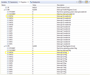
    Yet the above posted CCS register view has CPU register timer 2 IER bit is set.  Why there is No IRQ for the assigned vector shown below?  The MCU is revision B silicon, no advisory timer 2 fails to interrupt into assigned vector.

    Perhaps CPU timers 1/2 may need manual clear IFR or is that automatic? 

    Interrupt_register(INT_TIMER2, &NexVarsISR);

    Who ever decided to make Timer 0 into group1 has never tested calls from Timer 0 with FAST estimator enabled. Timer 0 is highly disruptive to motor control code, reason CPU timer 1 or 2 the only other option. Group1 ADCC1 interrupt gets out of phase with CPU timer 0 and GPIO pin monitoring main_ISR() decimation times jumps every clear ACK of CPU timer 0, PRD=500ms. Otherwise the GPIO is stable with CPU timer 0 stop and FAST estimator functions without interruptions.

  • FAST estimator is pure software algorithm which is independent of peripherals and doesn't use any interrupt. You just need to call the FAST functions in any periodic interrupt ISR as shown in example labs.

    The CPU timer 1 is used as a virtual timer in background loop, which is not must-have for the lab and is not related to FAST estimator.

    Please refer to Timer example in C2000 Ware as Veena mentioned above if you want to use the CPU timer.

  • You just need to call the FAST functions in any periodic interrupt ISR as shown in example labs

    The motor control SDK uses ADCC1 interrupt for FAST estimator main_ISR() vector (INT1.3) and it don't like being interrupted by Timer 0 in the same group1 clear ACK. Every time Timer0 ISR is cleared (500ms down count) FAST estimator losses synchronization, phase current jumps from the interruption of Timer 0.

    You just need to call the FAST functions in any periodic interrupt ISR as shown in example labs.

    The FAST estimator relies on ADCC1 triggers via EPWM CMPD synchronize current inside sector angles, ADCC1 interrupts via SOC main_ISR(). 

    There are no other periodic ISR in any MCU other than a timers or peripheral interrupts. Please see TRM table 3.3 for all x49c IRQ channel lineup.  

    Please refer to Timer example in C2000 Ware as Veena mentioned above if you want to use the CPU timer.

    Timer 1 and 2 are not vectoring to interrupt handler, hence that leaves timer 0 vector for any other polling actions and FAST estimator can not function correctly with Timer 0 ISR in group1.

    CPU timers 1 and 2 are not vectoring to the assigned ISR only timer 0 ePIE connected timer is functional to vector ISR.

  • The one difference is the SDK did not have a interrupt vector table like the timer example. Yet the SCIB vectors to his ISR.

    The timers example project incorrectly has CPU timers 1,2 placed inside a PIE vector table.  Yet CPU 1,2 timer interrupts are not even connected to ePIE they are CPU interrupt INT13, INT14 respectively.

  • PIE_RESERVED_ISR, // Reserved
    PIE_RESERVED_ISR, // Reserved
    PIE_RESERVED_ISR, // Reserved
    PIE_RESERVED_ISR, // Reserved
    PIE_RESERVED_ISR, // Reserved
    TIMER1_ISR, // CPU Timer 1 Interrupt
    TIMER2_ISR, // CPU Timer 2 Interrupt
    DATALOG_ISR, // Datalogging Interrupt
    RTOS_ISR, // RTOS Interrupt
    EMU_ISR, // Emulation Interrupt
    NMI_ISR, // Non-Maskable Interrupt
    ILLEGAL_ISR, // Illegal Operation Trap
    USER1_ISR, // User Defined Trap 1
    USER2_ISR, // User Defined Trap 2
    USER3_ISR, // User Defined Trap 3
    USER4_ISR, // User Defined Trap 4
    USER5_ISR, // User Defined Trap 5
    USER6_ISR, // User Defined Trap 6
    USER7_ISR, // User Defined Trap 7
    USER8_ISR, // User Defined Trap 8
    USER9_ISR, // User Defined Trap 9
    USER10_ISR, // User Defined Trap 10
    USER11_ISR, // User Defined Trap 11
    USER12_ISR, // User Defined Trap 12
    ADCA1_ISR, // 1.1 - ADCA Interrupt 1
    ADCB1_ISR, // 1.2 - ADCB Interrupt 1
    ADCC1_ISR, // 1.3 - ADCC Interrupt 1
    XINT1_ISR, // 1.4 - XINT1 Interrupt
    XINT2_ISR, // 1.5 - XINT2 Interrupt

  • Why don’t you us the EPWM timer or ADC triggered by EPWM event as the periodic interrupt for motor control as shown in motor control SDK?

    If you still want to use the CPU timer 0/1/2 interrupt, you can refer to the timer example in C2000Ware that shows how to use the CPU timer interrupt.

    You should define a ISR name and assign the address of the ISR to the interrupt vector as mentioned above.

  • Why don’t you us the EPWM timer or ADC triggered by EPWM event as the periodic interrupt for motor control as shown in motor control SDK?

    What do you think I have been trying to get working other than motor control FAST estimator gets interrupt by CPU timer 0 in ADCC1 group 1. The motor control SDK is not configured correctly with a proper vector table. Attempts to add vector table C2000 timers example added to SDK ends in compiler symbol errors for some crazy unrelated function. CPU timer 1&2 seemingly require a full vector table, not the default interrupt vectors derived via (interrupt.h) SDK Default vector method.  

    The C2000 timers example is not implementing driverlib calls and leverages mostly project Macros. Makes calls to (pievect.c, piectrl.c) to create a vector table with CPU timers 1&2 included. Testing the motor control SDK with intended CPU interrupts proves CPU Timer 0 can not be used at all and timer 1 and 2 are useless without functional interrupt vectors. Spent way to much time trying to get CPU interrupts to work with FAST estimator projects.

    You should define a ISR name and assign the address of the ISR to the interrupt vector as mentioned above

    That does not work with the SDK, only ePIE Timer 0 will vector to a handler. The motor control SDK (interrupt.c/h) are not producing a proper vector table and CPU timers 1/2 can not vector to the registered handler.

    The C2000 x49c devices timer examples dated {Release Date: Fri Feb 12 18:57:27 IST 2021} are not using driverlib calls to register CPU vector intrrupts. Why does Others MCU forum discourage the use of HWREG call macros and C2000 examples are very project specific C files do not port easily into other projects.

    CCS IDE and TM4C1294 project variant creates an interrupt vector table for all MCU peripherals, why C2000 projects do not?

    Table 3-3 shows CPU timer 0 can preempt ADCC1 for use by FAST estimator mainISR(). Only leaves CPU timer 1 or 2 to handle motor.vars output data without CCS debug real time silicon controls in the loop.

  • I am not sure that I can fully understand your questions above. As mentioned above, it's better to use the ADC or EPWM interrupt for motor control with Instaspin-foc, especially the current senor is the shunt resistor on low side. You can still add any peripheral interrupts into the instaspin-foc labs refer to the examples in C2000Ware since the instaspin labs are also based on driverlib in C2000Ware.

    You might take a look at the link below if you want to use interrupt nesting. https://software-dl.ti.com/C2000/docs/c28x_interrupt_nesting/html/index.html This one answers the question about how nesting interrupts can be supported on the C2000.


    Please take a look at DriverLib example 

    C:\ti\C2000\C2000Ware_<version>\driverlib\f28004x\examples\interrupt\interrupt_ex2_sw_prioritization

    This example illustrates how sw prioritization can be used for nested interrupts.


    In addition, Please have a look at this training material as well:  https://training.ti.com/c2000-f28004x-microcontroller-workshop?cu=1137791  This is a general link that is applicable to the F28004x device. 

  • I am not sure that I can fully understand your questions above

    Why does the SDK not have a vector table and CPU timer 2 will not vector when configured? This issue of CPU timer 0 effecting FAST estimator IRQ's is not nesting interrupts but pending IRQ's preempting ADCC1 ISR. Timer 0 has it's own ISR is not nesting inside FAST estimator ISR is preempted by ePIE before it clear ACK's even from the bottom of while loop. These are independent ISR's but exist in the same group 1. That is not nesting since ePIE controller should be managing pends and preemption based on clear ACK's posting within each ISR.

    It seems FAST estimator ISR driven by ADCC1 IRQ is not running synchronous with SYSCLK as it can be effected by CPU timer 0 period (500ms)  preempting FAST estimators execution time even EPWM ticks being >150µs does not stop TM0 from over running EPWM tick counts window for Instspin.  That is why CPU timer 2 is the only other possible solution but the SDK vector handler (interrupt.h) is not properly working to support CPU interrupts 13 and 14 since they never pend or preempt group1 ISR ADCC1 IRQ. 

  • As mentioned above and repeat at here again. The device driver for Instaspin-foc with FAST in motor control SDK is based on the driver lib in C2000Ware, you can refer to the example in C2000Ware to add any interrupts in the labs in motorControlSDK, the instaspin-foc doesn't limit you to use any other interrupts, just provide an example to use the periodic ADC interrupt for motor control, the ADC/PWM used by the motor control is easy to achieve the real time control with the latest current and voltage sampling results.

    You can take a look at the links recommend above if you want to understand the C2000 interrupts and how to use them in your project.

    Or you can refer to the lab12 in motor control SDK that uses CPU timer_0 and ADC interrupt for instaspin-foc with online variable switching frequency if you still have questions.

  • Or you can refer to the lab12 in motor control SDK that uses CPU timer_0 and ADC interrupt for instaspin-foc with online variable switching frequency if you still have questions.

    Yet I used CPU timer 0 in lab7 (500ms) period and it interrupts FAST estimator, it likely will do the same in lab12 if the period is >50µs. CPU timer 0 pends and preempts before ADCC1 IRQ sends clear ACK in lab7 placed at bottom of ISR return. How is it any different from coding a custom Instaspin application and enabling the very same CPU timers? Point is the same interrupt failures will occur using the format of any lab showing us to be the proper use of FAST estimator calls. Seemingly the engineer was unaware of this CPU interrupt failure conditions.

    instaspin-foc doesn't limit you to use any other interrupts,

    Actually that is not true since CPU timer 1 and timer 2 refuse to vector to registered ISR when configured into lab7. CPU timer 1 was not doing much of anything that can be traced to another SDK function. Timer 1 was only configured to check period overflow and clear when or if it does inside mainISR(). Again the SDK does not have a vector table and does not support CPU timers 1 or 2 thus allow anyone to investigate feasibility outside of CCS debug.  The use of interrupt.h to produce a default vector table only works with ePIE interrupts, does not work with CPU INT13 or INT14. Yet interrupt.h makes anyone believe CPU INT13 or INT14 should vector to ISR and was fully tested to do so.

    The question is why does the default vector table not support CPU INT13 and INT14 or new errata? Sorry I don't comprehend the use of a imaginary interrupt vector table in this example application very confusing. The method of default vector table failure seems to stem from (interrupt.h) use to enable CPU INT13 or INT14 without a proper vector address even when the application registers either ISR.

    Testing the SDK code base to see how flexible CPU timers were to Instaspin interrupts: As mention several times CPU timer 0 (500ms) period can not be used, it interferes with ADCC1 ISR loop. That preemption CPU timer 0 occurs even with ADCC1 continuous interrupt errata patch enabled. So we must try to use CPU timer 1 or timer 2 to test it in lab7 but they do not vector to registered ISR. The motor control SDK can not support CPU timer 1 or 2 registered ISR vectors. CPU timer 0 priority preemption of ADCC1 ISR is highly disruptive to form proper sector angles. Please check this reported issue out when time permits.

  • Thanks for spending so much time on testing the SDK code with so many different application cases. I don't fully understand why do you need to use the CPU timer 1 and 2 for FAST, and you need to use Timer 1 and Time 2 except ADC/PWM interrupt used for motor control ISR?

    You can find the PIE interrupt definition in hw_ints.h, and specify the interrupt handler as below. You need to enable the interrupt as shown in C2000Ware. 

        Interrupt_register(INT_TIMER1, &mainISR);

        Interrupt_register(INT_TIMER2, &mainISR);

  • I don't fully understand why do you need to use the CPU timer 1 and 2 for FAST

    No I don't need to modify SDK ADCC1 mainISR() works fine but not with CPU timer 0 interrupt being enabled in the same group1. Timer 0 ISR somehow overruns ADCC1 used with FAST estimator. Setting ePWM interrupt tick count >2 (user.h) does not stop timer 0 from stomping on FAST estimator mainISR() before it clear ACK's. So current spikes as motor stalls every 500ms or whenever CPU timer 0 pends and IRQ. 

    Was attempting to make SCIB output real time motor data to serial control LCD that requires CPU timer 1 or 2. Neither one vectors to ISR as properly registered. There seems to be a problem with interrupt.h default vector table does not properly register CPU timers via SDK use of default and imaginary vector table. There is no C2000 vector table installed in the SDK software like there is in CPU timers example project.

    Again I tried to patch SDK with a full vector table imported from the CPU timers example but it fails to compile with an odd symbol error likely from device.h. The timers example is completely different in the way it registers ISR's for every peripheral and list a full vector table not found in the SDK.

    Oddly don't have this problem with Stellaris/Tiva CCS adds vector table part of the project variant MCU selected. There is always a full peripheral vector table inserted into the project when user chooses the MCU from drop down. Why has C2000 made it so difficult to add a vector table into the CCS project?

  • The SDK doesn't need a vector table to enable a ISR. These are the interrupt vector address definition in hw_ints.h. You can refer to the examples in C2000Ware to add any interrupts in SDK includes the CPU timer0/1/2 or SCIB you want, the address of ISR will be assigned to the interrupt vector accordingly by calling the function like Interrupt_register(INT_TIMER0, &cpuTimer0ISR);

    If you want to use the nesting interrupt, please refer to the example mentioned above.

  • The SDK doesn't need a vector table to enable a ISR.

    SCIB and CPU timer0  registered ISR vectors correctly via ePIE control of CPU interrupts. However CPU 1&2 timer interrupts are directly connected to the CPU and do not work after registering as below.   

    /* Stop CPU-TM2 for timebase reset */
    CPUTimer_stopTimer(CPUTIMER2_BASE);

     /* Register SCIB INT vectors for ISR handler  */                                                                                                                          Interrupt_register(INT_TIMER2, &cpuTimer2ISR); 

    /* Set PRD for 500ms load counts */
    CPUTimer_setPeriod(CPUTIMER2_BASE, 0xF5FE100);

    /* Enable timer 2 TIE bit local interrupt */
    CPUTimer_enableInterrupt(CPUTIMER2_BASE);

    /* Enable CPU-TM2 IER bit interrupt */
    Interrupt_enable(INT_TIMER2);

    If you want to use the nesting interrupt,

    Nesting an CPU timer interrupt inside another ISR is not being asserted by the application. There can exist several interrupts for any single group (Table 3-3 above), that is not considered nesting an interrupt inside another ISR. Again Group1 interrupt priority ordering is questionable.

    Even if IER and TIE bits are set enable for timer 2 it still refuses to vector into the registered ISR.

  • You might refer to the attached file. The three CPU timers can be used in SDK as the timer example in C2000Ware.

    //#############################################################################
    // $TI Release: MotorControl SDK v1.00.00.00 $
    // $Release Date: Mon Mar 11 18:37:41 CDT 2019 $
    // $Copyright:
    // Copyright (C) 2017-2018 Texas Instruments Incorporated - http://www.ti.com/
    //
    // Redistribution and use in source and binary forms, with or without
    // modification, are permitted provided that the following conditions
    // are met:
    //
    //   Redistributions of source code must retain the above copyright
    //   notice, this list of conditions and the following disclaimer.
    //
    //   Redistributions in binary form must reproduce the above copyright
    //   notice, this list of conditions and the following disclaimer in the
    //   documentation and/or other materials provided with the
    //   distribution.
    //
    //   Neither the name of Texas Instruments Incorporated nor the names of
    //   its contributors may be used to endorse or promote products derived
    //   from this software without specific prior written permission.
    //
    // THIS SOFTWARE IS PROVIDED BY THE COPYRIGHT HOLDERS AND CONTRIBUTORS
    // "AS IS" AND ANY EXPRESS OR IMPLIED WARRANTIES, INCLUDING, BUT NOT
    // LIMITED TO, THE IMPLIED WARRANTIES OF MERCHANTABILITY AND FITNESS FOR
    // A PARTICULAR PURPOSE ARE DISCLAIMED. IN NO EVENT SHALL THE COPYRIGHT
    // OWNER OR CONTRIBUTORS BE LIABLE FOR ANY DIRECT, INDIRECT, INCIDENTAL,
    // SPECIAL, EXEMPLARY, OR CONSEQUENTIAL DAMAGES (INCLUDING, BUT NOT
    // LIMITED TO, PROCUREMENT OF SUBSTITUTE GOODS OR SERVICES; LOSS OF USE,
    // DATA, OR PROFITS; OR BUSINESS INTERRUPTION) HOWEVER CAUSED AND ON ANY
    // THEORY OF LIABILITY, WHETHER IN CONTRACT, STRICT LIABILITY, OR TORT
    // (INCLUDING NEGLIGENCE OR OTHERWISE) ARISING IN ANY WAY OUT OF THE USE
    // OF THIS SOFTWARE, EVEN IF ADVISED OF THE POSSIBILITY OF SUCH DAMAGE.
    // $
    //#############################################################################
    
    //! \file   solutions/common/sensorless_foc/source/is07_speed_control.c
    //! \brief  This lab is used to implement the speed close loop control and how
    //!         to adjust the Kp and Ki terms in the PI speed controller
    //!
    
    // **************************************************************************
    
    //
    // solutions
    //
    #include "labs.h"
    
    #pragma CODE_SECTION(mainISR, ".TI.ramfunc");
    
    //#####BEGIN_INTERNAL#####
    #ifdef CPUTIMER_TEST
    #include "sw_interrupt_prioritization_logic.h"
    #include "sw_prioritized_isr_levels.h"
    #endif // CPUTIMER_TEST
    //#####END_INTERNAL#######
    
    //
    // the globals
    //
    HAL_ADCData_t adcData = {{0.0, 0.0, 0.0}, {0.0, 0.0, 0.0}, 0.0};
    
    HAL_PWMData_t pwmData = {{0.0, 0.0, 0.0}};
    
    uint16_t counterLED = 0;  //!< Counter used to divide down the ISR rate for
                               //!< visually blinking an LED
    
    uint16_t counterSpeed = 0;
    uint16_t counterTrajSpeed = 0;
    uint16_t counterTrajId = 0;
    
    uint32_t offsetCalcCount = 0;     //!< Counter used to count the wait time
                                      //!< for offset calibration, unit: ISR cycles
    
    uint32_t offsetCalcWaitTime = 50000;  //!< Wait time setting for current/voltage
                                          //!< offset calibration, unit: ISR cycles
    
    EST_InputData_t estInputData = {0, {0.0, 0.0}, {0.0, 0.0}, 0.0, 0.0};
    
    EST_OutputData_t estOutputData = {0, 0.0, 0.0, 0.0, 0.0, 0.0, 0.0,
                                      {0.0, 0.0}, {0.0, 0.0}, 0, 0.0};
    float32_t angleDelta_rad;   //!< the rotor angle compensation value
    float32_t angleFoc_rad;     //!< the rotor angle for FOC modules
    
    MATH_Vec2 Idq_ref_A;        //!< the reference current on d&q rotation axis
    MATH_Vec2 Idq_offset_A;     //!< the offsetting current on d&q rotation axis
    MATH_Vec2 Iab_in_A;         //!< the alpha&beta axis current are converter from
                                //!< 3-phase sampling input current of motor
    MATH_Vec2 Idq_in_A;         //!< the d&q axis current are converter from
                                //!< 3-phase sampling input current of motor
    MATH_Vec2 Vab_out_V;        //!< the output control voltage on alpha&beta axis
    MATH_Vec2 Vdq_out_V;        //!< the output control voltage on d&q axis
    
    USER_Params userParams;    //!< the user parameters for motor control
                                //!< and hardware board configuration
    #pragma DATA_SECTION(userParams, "ctrl_data");
    
    volatile MOTOR_Vars_t motorVars = MOTOR_VARS_INIT;
    #pragma DATA_SECTION(motorVars, "ctrl_data");
    
    HAL_Handle    halHandle;     //!< the handle for the hardware abstraction layer
    HAL_Obj       hal;           //!< the hardware abstraction layer object
    
    EST_Handle    estHandle;        //!< the handle for the estimator
    
    CTRL_Handle   ctrlHandle;       //!< the handle for the controller
    CTRL_Obj      ctrl;             //!< the controller object
    
    CLARKE_Handle clarkeHandle_I;   //!< the handle for the current Clarke transform
    CLARKE_Obj    clarke_I;         //!< the current Clarke transform object
    
    CLARKE_Handle clarkeHandle_V;   //!< the handle for the voltage Clarke transform
    CLARKE_Obj    clarke_V;         //!< the voltage Clarke transform object
    
    IPARK_Handle  iparkHandle;      //!< the handle for the inverse Park transform
    IPARK_Obj     ipark;            //!< the inverse Park transform object
    
    PARK_Handle   parkHandle;       //!< the handle for the Park object
    PARK_Obj      park;             //!< the Park transform object
    
    PI_Handle     piHandle_Id;      //!< the handle for the Id PI controller
    PI_Obj        pi_Id;            //!< the Id PI controller object
    
    PI_Handle     piHandle_Iq;      //!< the handle for the Iq PI controller
    PI_Obj        pi_Iq;            //!< the Iq PI controller object
    
    PI_Handle     piHandle_fwc;     //!< the handle for the Iq PI controller
    PI_Obj        pi_fwc;           //!< the Iq PI controller object
    
    PI_Handle     piHandle_spd;     //!< the handle for the speed PI controller
    PI_Obj        pi_spd;           //!< the speed PI controller object
    
    SVGEN_Handle  svgenHandle;      //!< the handle for the space vector generator
    SVGEN_Obj     svgen;            //!< the space vector generator object
    
    TRAJ_Handle   trajHandle_spd; //!< the handle for the speed reference trajectory
    TRAJ_Obj      traj_spd;       //!< the speed reference trajectory object
    
    TRAJ_Handle   trajHandle_Id;    //!< the handle for the id reference trajectory
    TRAJ_Obj      traj_Id;          //!< the id reference trajectory object
    
    TRAJ_Handle   trajHandle_fwc;   //!< the handle for the id reference trajectory
    TRAJ_Obj      traj_fwc;         //!< the id reference trajectory object
    
    //!< the handles for the current offset calculation
    FILTER_FO_Handle  filterHandle_I[USER_NUM_CURRENT_SENSORS];
    //!< the current offset calculation
    FILTER_FO_Obj     filter_I[USER_NUM_CURRENT_SENSORS];
    
    //!< the handles for the voltage offset calculation
    FILTER_FO_Handle  filterHandle_V[USER_NUM_VOLTAGE_SENSORS];
    //!< the voltage offset calculation
    FILTER_FO_Obj     filter_V[USER_NUM_VOLTAGE_SENSORS];
    
    MATH_Vec2 IdqSet_A = {0.0, 0.0};
    
    #ifdef DRV8320_SPI
    //
    // Watch window interface to the 8320 SPI
    //
    DRV8320_SPIVars_t drvSPI8320Vars;
    #pragma DATA_SECTION(drvSPI8320Vars, "ctrl_data");
    #endif
    
    #ifdef PWMDAC_ENABLE
    HAL_PWMDACData_t pwmDACData;
    
    #pragma DATA_SECTION(pwmDACData, "ctrl_data");
    #endif  // PWMDAC_ENABLE
    
    //#####BEGIN_INTERNAL#####
    // TODO: cpuTime
    #ifdef CPUTIME_ENABLE
    // define CPU time for performance test
    uint32_t timer1Cnt;
    uint32_t timer2Cnt;
    
    CPU_TIME_Obj     cpuTime;
    CPU_TIME_Handle  cpuTimeHandle;
    #endif // CPUTIME_ENABLE
    //#####END_INTERNAL#######
    
    //#####BEGIN_INTERNAL#####
    #ifdef CPUTIMER_TEST
    // Function Prototypes
    __interrupt void cpuTimer0ISR(void);
    __interrupt void cpuTimer1ISR(void);
    __interrupt void cpuTimer2ISR(void);
    void initCPUTimers(void);
    void configCPUTimer(uint32_t, float, float);
    
    // variables
    uint32_t cpuTimer0IntCount;
    uint32_t cpuTimer1IntCount;
    uint32_t cpuTimer2IntCount;
    
    // This array will be used as a trace to check the
    // order that the interrupts were serviced
    #define TRACE_SIZE  63U
    uint32_t  traceISR[TRACE_SIZE];
    
    //
    // Index to update an element in the trace buffer
    uint32_t  traceISRIndex = 0;
    #endif // CPUTIMER_TEST
    //#####END_INTERNAL#######
    
    #ifdef _STEP_RESPONSE_EN_
    
    #define SPEED_CHANGE_FREQ_Hz  (float32_t) (1.0)         // 2 seconds
    
    float32_t speedRefLow_Hz  = (1000.0f / 60.0f * USER_MOTOR_NUM_POLE_PAIRS);   // 1000rpm
    float32_t speedRefHigh_Hz = (3000.0f / 60.0f * USER_MOTOR_NUM_POLE_PAIRS);   // 2000rpm
    uint32_t  speedISRCounter = 0;
    uint16_t  speedSetProfile = 0;
    
    #endif  // _STEP_RESPONSE_EN_
    
    #ifdef _FLASH
    uint32_t timeWaitCnt = 0;
    #endif
    
    //
    // the functions
    //
    
    void main(void)
    {
        uint16_t estNumber = 0;
        bool flagEstStateChanged = false;
    
    #ifdef _HVKIT_REV1p1_
        motorVars.boardKit = BOARD_HVMTRPFC_REV1P1;
    #endif // _HVKIT_REV1p1_
    
    #ifdef _DRV8301_KIT_REVD_
        motorVars.boardKit = BOARD_DRV8301_REVD;
    #endif  // _DRV8301_KIT_REVD_
    
    #ifdef _BOOSTXL_8320RS_REVA_
        motorVars.boardKit = BOARD_BSXL8320RS_REVA;
    #endif  // _BOOSTXL_8320RS_REVA_
    
        //
        // initialize the user parameters
        //
        USER_setParams(&userParams);
    
        userParams.flag_bypassMotorId = true;
    
        //
        // initialize the user parameters
        //
        USER_setParams_priv(&userParams);
    
        //
        // initialize the driver
        //
        halHandle = HAL_init(&hal, sizeof(hal));
    
        //
        // set the driver parameters
        //
        HAL_setParams(halHandle);
    
        //
        // initialize the Clarke modules
        //
        clarkeHandle_I = CLARKE_init(&clarke_I, sizeof(clarke_I));
        clarkeHandle_V = CLARKE_init(&clarke_V, sizeof(clarke_V));
    
        //
        // set the Clarke parameters
        //
        setupClarke_I(clarkeHandle_I, userParams.numCurrentSensors);
        setupClarke_V(clarkeHandle_V, userParams.numVoltageSensors);
    
        //
        // initialize the estimator
        //
        estHandle = EST_initEst(estNumber);
    
        //
        // set the default estimator parameters
        //
        EST_setParams(estHandle, &userParams);
        EST_setFlag_enableForceAngle(estHandle, motorVars.flagEnableForceAngle);
        EST_setFlag_enableRsRecalc(estHandle, motorVars.flagEnableRsRecalc);
    
        // set the scale factor for high frequency motor
        EST_setOneOverFluxGain_sf(estHandle, &userParams, USER_EST_FLUX_HF_SF);
        EST_setFreqLFP_sf(estHandle, &userParams, USER_EST_FREQ_HF_SF);
        EST_setBemf_sf(estHandle, &userParams, USER_EST_BEMF_HF_SF);
    
        //
        // if motor is an induction motor, configure default state of PowerWarp
        //
        if(userParams.motor_type == MOTOR_TYPE_INDUCTION)
        {
            EST_setFlag_enablePowerWarp(estHandle, motorVars.flagEnablePowerWarp);
            EST_setFlag_bypassLockRotor(estHandle, motorVars.flagBypassLockRotor);
        }
    
        //
        // initialize the inverse Park module
        //
        iparkHandle = IPARK_init(&ipark, sizeof(ipark));
    
        //
        // initialize the Park module
        //
        parkHandle = PARK_init(&park, sizeof(park));
    
        //
        // initialize the PI controllers
        //
        piHandle_Id  = PI_init(&pi_Id, sizeof(pi_Id));
        piHandle_Iq  = PI_init(&pi_Iq, sizeof(pi_Iq));
        piHandle_fwc = PI_init(&pi_fwc, sizeof(pi_fwc));
        piHandle_spd = PI_init(&pi_spd, sizeof(pi_spd));
    
        //
        // setup the controllers, speed, d/q-axis current pid regulator
        //
        setupControllers();
    
        //
        // initialize the space vector generator module
        //
        svgenHandle = SVGEN_init(&svgen, sizeof(svgen));
    
        //
        // initialize the speed reference trajectory
        //
        trajHandle_spd = TRAJ_init(&traj_spd, sizeof(traj_spd));
    
        //
        // configure the speed reference trajectory (Hz)
        //
        TRAJ_setTargetValue(trajHandle_spd, 0.0);
        TRAJ_setIntValue(trajHandle_spd, 0.0);
        TRAJ_setMinValue(trajHandle_spd, -USER_MOTOR_FREQ_MAX_HZ);
        TRAJ_setMaxValue(trajHandle_spd, USER_MOTOR_FREQ_MAX_HZ);
        TRAJ_setMaxDelta(trajHandle_spd, (USER_MAX_ACCEL_Hzps / USER_ISR_FREQ_Hz));
    
        //
        // initialize the Id reference trajectory
        //
        trajHandle_Id = TRAJ_init(&traj_Id, sizeof(traj_Id));
    
        //
        // configure the Id reference trajectory
        //
        TRAJ_setTargetValue(trajHandle_Id, 0.0);
        TRAJ_setIntValue(trajHandle_Id, 0.0);
        TRAJ_setMinValue(trajHandle_Id, -USER_MOTOR_MAX_CURRENT_A);
        TRAJ_setMaxValue(trajHandle_Id,  USER_MOTOR_MAX_CURRENT_A);
        TRAJ_setMaxDelta(trajHandle_Id,
                         (USER_MOTOR_RES_EST_CURRENT_A / USER_ISR_FREQ_Hz));
    
        //
        // initialize the fwc reference trajectory
        //
        trajHandle_fwc = TRAJ_init(&traj_fwc, sizeof(traj_fwc));
    
        //
        // configure the fwc reference trajectory
        //
        TRAJ_setTargetValue(trajHandle_fwc, 0.0);
        TRAJ_setIntValue(trajHandle_fwc, 0.0);
        TRAJ_setMinValue(trajHandle_fwc, -USER_MOTOR_MAX_CURRENT_A);
        TRAJ_setMaxValue(trajHandle_fwc,  USER_MOTOR_MAX_CURRENT_A);
        TRAJ_setMaxDelta(trajHandle_fwc,
                         (USER_MOTOR_RES_EST_CURRENT_A / USER_ISR_FREQ_Hz));
    
        //
        // initialize and configure offsets using first-order filter
        //
        {
            //
            // Sets the first-order filter denominator coefficients
            // a1, the filter coefficient value for z^(-1)
            // b0, the filter coefficient value for z^0
            // b1, the filter coefficient value for z^(-1)
            //
            uint16_t cnt = 0;
            float32_t b0 = userParams.offsetPole_rps / userParams.ctrlFreq_Hz;
            float32_t a1 = (b0 - 1.0);
            float32_t b1 = 0.0;
    
            //
            // For Current offset calibration filter
            //
            for(cnt = 0; cnt < USER_NUM_CURRENT_SENSORS; cnt++)
            {
                filterHandle_I[cnt] = FILTER_FO_init(&filter_I[cnt],
                                                       sizeof(filter_I[cnt]));
    
                FILTER_FO_setDenCoeffs(filterHandle_I[cnt], a1);
                FILTER_FO_setNumCoeffs(filterHandle_I[cnt], b0, b1);
    
                FILTER_FO_setInitialConditions(filterHandle_I[cnt],
                                            motorVars.offsets_I_A.value[cnt],
                                            motorVars.offsets_I_A.value[cnt]);
            }
    
            //
            // For Voltage offset calibration filter
            //
            for(cnt = 0; cnt < USER_NUM_VOLTAGE_SENSORS; cnt++)
            {
                filterHandle_V[cnt] = FILTER_FO_init(&filter_V[cnt],
                                                       sizeof(filter_V[cnt]));
    
                FILTER_FO_setDenCoeffs(filterHandle_V[cnt], a1);
                FILTER_FO_setNumCoeffs(filterHandle_V[cnt], b0, b1);
    
                FILTER_FO_setInitialConditions(filterHandle_V[cnt],
                                            motorVars.offsets_V_V.value[cnt],
                                            motorVars.offsets_V_V.value[cnt]);
            }
    
            motorVars.flagEnableOffsetCalc = true;
            offsetCalcCount = 0;
        }
    
        motorVars.faultMask.all = FAULT_MASK_ALL_FLTS;
    
        //#####BEGIN_INTERNAL#####
        // TODO: CPU_TIME_init()
        #ifdef CPUTIME_ENABLE
        // initialize the CPU usage module
        cpuTimeHandle = CPU_TIME_init(&cpuTime, sizeof(cpuTime));
        CPU_TIME_reset(cpuTimeHandle);
        #endif // CPUTIME_ENABLE
        //#####END_INTERNAL#######
    
    #ifdef PWMDAC_ENABLE
        // set DAC parameters
        pwmDACData.periodMax =
                PWMDAC_getPeriod(halHandle->pwmDACHandle[PWMDAC_NUMBER_1]);
    
        pwmDACData.ptrData[0] = &adcData.I_A.value[0];
        pwmDACData.ptrData[1] = &adcData.I_A.value[1];
        pwmDACData.ptrData[2] = &adcData.V_V.value[0];
        pwmDACData.ptrData[3] = &adcData.V_V.value[1];
    
        pwmDACData.offset[0] = 1.0;     // Change -1.0~1.0 to 0~1.0 for pwmDac
        pwmDACData.offset[1] = 0.5;     // Change -1.0~1.0 to 0~1.0 for pwmDac
        pwmDACData.offset[2] = 0.5;     // Change -1.0~1.0 to 0~1.0 for pwmDac
        pwmDACData.offset[3] = 0.5;     // Change -1.0~1.0 to 0~1.0 for pwmDac
    
        pwmDACData.gain[0] = -MATH_ONE_OVER_TWO_PI;  // Convert -PI()~PI() to 0~1.0
        pwmDACData.gain[1] = 1.0 / USER_ADC_FULL_SCALE_CURRENT_A;
        pwmDACData.gain[2] = 1.0 / USER_ADC_FULL_SCALE_VOLTAGE_V;
        pwmDACData.gain[3] = 1.0 / USER_ADC_FULL_SCALE_CURRENT_A;
    #endif  // PWMDAC_ENABLE
    
    #ifdef DATALOG_ENABLE
        // Initialize Datalog
        datalogHandle = DATALOG_init(&datalog, sizeof(datalog));
        DATALOG_Obj *datalogObj = (DATALOG_Obj *)datalogHandle;
    
        HAL_resetDlogWithDMA();
        HAL_setupDlogWithDMA(halHandle, 0, &datalogBuff1[0], &datalogBuff1[1]);
        HAL_setupDlogWithDMA(halHandle, 1, &datalogBuff2[0], &datalogBuff2[1]);
        #if (DATA_LOG_BUFF_NUM == 4)
        HAL_setupDlogWithDMA(halHandle, 2, &datalogBuff3[0], &datalogBuff3[1]);
        HAL_setupDlogWithDMA(halHandle, 3, &datalogBuff4[0], &datalogBuff4[1]);
        #endif  // DATA_LOG_BUFF_NUM == 4
    
        // set datalog parameters
        datalogObj->iptr[0] = &adcData.I_A.value[0];
        datalogObj->iptr[1] = &adcData.I_A.value[1];
        #if (DATA_LOG_BUFF_NUM == 4)
        datalogObj->iptr[2] = &adcData.V_V.value[0];
        datalogObj->iptr[3] = &adcData.V_V.value[1];
        #endif  // DATA_LOG_BUFF_NUM == 4
    #endif  // DATALOG_ENABLE
    
    #ifdef _STEP_RESPONSE_EN_
        GRAPH_DataPointerInit(&gStepVars,
                              &motorVars.speed_Hz,
                              &Idq_in_A.value[0], &Idq_in_A.value[1],
                              &motorVars.speedRef_Hz,
                              &Idq_ref_A.value[0], &Idq_ref_A.value[1]);
    #endif  // _STEP_RESPONSE_EN_
    
        //
        // setup faults
        //
        HAL_setupFaults(halHandle);
    
    #ifdef DRV8320_SPI
        //
        // turn on the DRV8320 if present
        //
        HAL_enableDRV(halHandle);
    
        //
        // initialize the DRV8320 interface
        //
        HAL_setupDRVSPI(halHandle, &drvSPI8320Vars);
    
        drvSPI8320Vars.Ctrl_Reg_05.VDS_LVL = DRV8320_VDS_LEVEL_1P300_V;
        drvSPI8320Vars.Ctrl_Reg_05.DEAD_TIME = DRV8320_DEADTIME_100_NS;
        drvSPI8320Vars.writeCmd = 1;
    
        HAL_writeDRVData(halHandle, &drvSPI8320Vars);
    
        drvSPI8320Vars.readCmd = 1;
        HAL_readDRVData(halHandle, &drvSPI8320Vars);
    #endif
    
        //
        // Set some global variables
        //
        motorVars.pwmISRCount = 0;          // clear the counter
        motorVars.speedRef_Hz = 50.0;       // set reference frequency to 20.0Hz
        motorVars.accelerationMax_Hzps = 20.0;
        motorVars.accelerationStart_Hzps = 5.0;
    
        motorVars.flagEnableOffsetCalc = true;
    
        //
        // disable the PWM
        //
        HAL_disablePWM(halHandle);
    
        //
        // initialize the interrupt vector table
        //
        HAL_initIntVectorTable(halHandle);
    
        //
        // enable the ADC interrupts
        //
        HAL_enableADCInts(halHandle);
    
        //#####BEGIN_INTERNAL#####
        #ifdef CPUTIMER_TEST
    
        // ISRs for each CPU Timer interrupt
        Interrupt_register(INT_TIMER0, &cpuTimer0ISR);
        Interrupt_register(INT_TIMER1, &cpuTimer1ISR);
        Interrupt_register(INT_TIMER2, &cpuTimer2ISR);
    
        // Reset the ISR trace
        uint16_t i;
    
        for(i = 0; i < TRACE_SIZE; i++)
        {
           traceISR[i] = 0;
        }
    
        // Initializes the Device Peripheral. For this example, only initialize the
        // Cpu Timers.
        initCPUTimers();
    
        // Configure CPU-Timer 0, 1, and 2 to interrupt every second:
        // 1 second Period (in uSeconds)
        configCPUTimer(CPUTIMER0_BASE, DEVICE_SYSCLK_FREQ, 10000);        // 0.01s
        configCPUTimer(CPUTIMER1_BASE, DEVICE_SYSCLK_FREQ, 20000);        // 0.02s
        configCPUTimer(CPUTIMER2_BASE, DEVICE_SYSCLK_FREQ, 40000);        // 0.04s
    
        // To ensure precise timing, use write-only instructions to write to the
        // entire register. Therefore, if any of the configuration bits are changed
        // in configCPUTimer and initCPUTimers, the below settings must also
        // be updated.
        CPUTimer_enableInterrupt(CPUTIMER0_BASE);
        CPUTimer_enableInterrupt(CPUTIMER1_BASE);
        CPUTimer_enableInterrupt(CPUTIMER2_BASE);
    
        // Enables CPU int1, int13, and int14 which are connected to CPU-Timer 0,
        // CPU-Timer 1, and CPU-Timer 2 respectively.
        // Enable TINT0 in the PIE: Group 1 interrupt 7
        Interrupt_enable(INT_TIMER0);
        Interrupt_enable(INT_TIMER1);
        Interrupt_enable(INT_TIMER2);
    
        // Starts CPU-Timer 0, CPU-Timer 1, and CPU-Timer 2.
        CPUTimer_startTimer(CPUTIMER0_BASE);
        CPUTimer_startTimer(CPUTIMER1_BASE);
        CPUTimer_startTimer(CPUTIMER2_BASE);
    
        #endif // CPUTIMER_TEST
        //#####END_INTERNAL#######
    
        //
        // disable global interrupts
        //
        HAL_enableGlobalInts(halHandle);
    
        //
        // enable debug interrupts
        //
        HAL_enableDebugInt(halHandle);
    
        //
        // Waiting for enable system flag to be set
        //
        while(motorVars.flagEnableSys == false)
        {
    #ifdef _FLASH
            timeWaitCnt++;
    
            if(timeWaitCnt > 250000)
            {
                timeWaitCnt = 0;
                motorVars.flagEnableSys = true;
                motorVars.flagRunIdentAndOnLine = false;    // Change to "true"
            }
    #endif
        }
    
        //
        // loop while the enable system flag is true
        //
        while(motorVars.flagEnableSys == true)
        {
    
            //#####BEGIN_INTERNAL#####
            #ifndef CPUTIMER_TEST
            //#####END_INTERNAL#######
            //
            // 1ms time base
            //
            if(HAL_getTimerStatus(halHandle, HAL_CPU_TIMER1))
            {
                motorVars.timerCnt_1ms++;
    
                HAL_clearTimerFlag(halHandle, HAL_CPU_TIMER1);
            }
    
            //#####BEGIN_INTERNAL#####
             #endif // CPUTIMER_TEST
             //#####END_INTERNAL#######
    
            motorVars.mainLoopCount++;
    
            //
            // set the reference value for internal DACA and DACB
            //
            HAL_setDACValue(halHandle, 0, motorVars.dacaVal);
            HAL_setDACValue(halHandle, 1, motorVars.dacbVal);
    
            //
            // set internal DAC value for on-chip comparator for current protection
            //
            {
                uint16_t  cmpssCnt;
    
                for(cmpssCnt = 0; cmpssCnt < HAL_NUM_CMPSS_CURRENT; cmpssCnt++)
                {
                    HAL_setCMPSSDACValueHigh(halHandle,
                                             cmpssCnt, motorVars.dacValH);
    
                    HAL_setCMPSSDACValueLow(halHandle,
                                            cmpssCnt, motorVars.dacValL);
                }
            }
    
            //
            // enable or disable force angle
            //
            EST_setFlag_enableForceAngle(estHandle,
                                         motorVars.flagEnableForceAngle);
    
            //
            // enable or disable bypassLockRotor flag
            //
            if(userParams.motor_type == MOTOR_TYPE_INDUCTION)
            {
                EST_setFlag_bypassLockRotor(estHandle,
                                            motorVars.flagBypassLockRotor);
            }
    
            if(HAL_getPwmEnableStatus(halHandle) == true)
            {
                if(HAL_getTripFaults(halHandle) != 0)
                {
                    motorVars.faultNow.bit.moduleOverCurrent = 1;
                }
            }
    
            motorVars.faultUse.all =
                    motorVars.faultNow.all & motorVars.faultMask.all;
    
            //
            // Had some faults to stop the motor
            //
            if(motorVars.faultUse.all != 0)
            {
                motorVars.flagRunIdentAndOnLine = 0;
            }
    
            if((motorVars.flagRunIdentAndOnLine == true) &&
               (motorVars.flagEnableOffsetCalc == false))
            {
                //
                // enable the estimator
                //
                EST_enable(estHandle);
    
                //
                // enable the trajectory generator
                //
                EST_enableTraj(estHandle);
    
                if(HAL_getPwmEnableStatus(halHandle) == false)
                {
    
                    //
                    // enable the PWM
                    //
                    HAL_enablePWM(halHandle);
                }
    
                //
                // set the reference to the trajectory of speed
                //
                TRAJ_setTargetValue(trajHandle_spd, motorVars.speedRef_Hz);
    
                //
                // set the acceleration to the trajectory of speed
                //
    
                if( fabsf(motorVars.speedRef_Hz) > SPEED_STARTUP_HZ)
                {
                    TRAJ_setMaxDelta(trajHandle_spd,
                               (motorVars.accelerationMax_Hzps / USER_ISR_FREQ_Hz));
                }
                else
                {
                    TRAJ_setMaxDelta(trajHandle_spd,
                               (motorVars.accelerationStart_Hzps / USER_ISR_FREQ_Hz));
                }
    
            }
            else if(motorVars.flagEnableOffsetCalc == false)
            {
                //
                // disable the estimator
                //
                EST_disable(estHandle);
    
                //
                // disable the trajectory generator
                //
                EST_disableTraj(estHandle);
    
                //
                // disable the PWM
                //
                HAL_disablePWM(halHandle);
    
                //
                // clear integral outputs of the controllers
                //
                PI_setUi(piHandle_Id, 0.0);
                PI_setUi(piHandle_Iq, 0.0);
                PI_setUi(piHandle_fwc, 0.0);
                PI_setUi(piHandle_spd, 0.0);
    
                //
                // clear current references
                //
                Idq_ref_A.value[0] = 0.0;
                Idq_ref_A.value[1] = 0.0;
    
                //
                // clear current offsets
                //
                Idq_offset_A.value[0] = 0.0;
                Idq_offset_A.value[1] = 0.0;
    
                //
                // get the magnetic current for ACIM
                //
                motorVars.IdRated_A = EST_getIdRated_A(estHandle);
    
                //
                // clear current and angle for FWC and MTPA
                //
                motorVars.VsRef_pu = USER_MAX_VS_MAG_PU;
                motorVars.IsRef_A = 0.0;
                motorVars.angleCurrent_rad = 0.0;
    
                //
                // clear the trajectory of speed
                //
                TRAJ_setTargetValue(trajHandle_spd, 0.0);
                TRAJ_setIntValue(trajHandle_spd, 0.0);
            }
    
            //
            // check the trajectory generator
            //
            if(EST_isTrajError(estHandle) == true)
            {
                //
                // disable the PWM
                //
                HAL_disablePWM(halHandle);
    
                //
                // set the enable system flag to false
                //
                motorVars.flagEnableSys = false;
            }
            else
            {
                //
                // update the trajectory generator state
                //
                EST_updateTrajState(estHandle);
            }
    
            //
            // check the estimator
            //
            if(EST_isError(estHandle) == true)
            {
                //
                // disable the PWM
                //
                HAL_disablePWM(halHandle);
    
                //
                // set the enable system flag to false
                //
                motorVars.flagEnableSys = false;
            }
            else        // No estimator error
            {
                motorVars.Id_target_A = EST_getIntValue_Id_A(estHandle);
    
                flagEstStateChanged = EST_updateState(estHandle, 0.0);
    
                if(flagEstStateChanged == true)
                {
                    //
                    // configure the trajectory generator
                    //
                    EST_configureTraj(estHandle);
                }
            }
    
            if(EST_isMotorIdentified(estHandle) == true)
            {
                if(motorVars.flagSetupController == true)
                {
                    //
                    // update the controller
                    // set custom current and speed controllers gains
                    //
                    updateControllers();
                }
                else
                {
                    motorVars.flagMotorIdentified = true;
                    motorVars.flagSetupController = true;
    
                    setupControllers();
                }
            }
            //
            // update the global variables
            //
            updateGlobalVariables(estHandle);
    
    #ifdef _STEP_RESPONSE_EN_
            // Generate Step response
             GRAPH_generateStepResponse(&gGraphVars, &gStepVars);
    #endif  //  _STEP_RESPONSE_EN_
    
    #ifdef DRV8320_SPI
            //
            // DRV8320 Read/Write
            //
            HAL_writeDRVData(halHandle, &drvSPI8320Vars);
    
            HAL_readDRVData(halHandle, &drvSPI8320Vars);
    #endif
        } // end of while() loop
    
        //
        // disable the PWM
        //
        HAL_disablePWM(halHandle);
    
    } // end of main() function
    
    //#####BEGIN_INTERNAL#####
    // TODO: mainISR()
    //#####END_INTERNAL#######
    __interrupt void mainISR(void)
    {
        //#####BEGIN_INTERNAL#####
        #ifdef CPUTIME_ENABLE
        // read the timer 1 value and update the CPU usage module
        timer1Cnt = HAL_readTimerCnt(halHandle, HAL_CPU_TIMER2);
        CPU_TIME_updateCnts(cpuTimeHandle, timer1Cnt, 0);
        #endif // CPUTIME_ENABLE
        //#####END_INTERNAL#######
    
        //#####BEGIN_INTERNAL#####
        //
        // check ISR executing time by toggling the GPIO
        //
        HAL_setGPIOHigh(halHandle, HAL_GPIO_ISR);
        //#####END_INTERNAL#######
    
        motorVars.pwmISRCount++;
    
        //
        // toggle status LED
        //
        counterLED++;
    
        if(counterLED > (uint32_t)(USER_ISR_FREQ_Hz / LED_BLINK_FREQ_Hz))
        {
            HAL_toggleLED(halHandle, HAL_GPIO_LED2);
            counterLED = 0;
        }
    
        //
        // acknowledge the ADC interrupt
        //
        HAL_ackADCInt(halHandle, ADC_INT_NUMBER1);
    
        //
        // read the ADC data with offsets
        //
        HAL_readADCDataWithOffsets(halHandle, &adcData);
    
        //
        // remove offsets
        //
        adcData.I_A.value[0] -= motorVars.offsets_I_A.value[0];
        adcData.I_A.value[1] -= motorVars.offsets_I_A.value[1];
        adcData.I_A.value[2] -= motorVars.offsets_I_A.value[2];
        adcData.V_V.value[0] -= motorVars.offsets_V_V.value[0] * adcData.dcBus_V;
        adcData.V_V.value[1] -= motorVars.offsets_V_V.value[1] * adcData.dcBus_V;
        adcData.V_V.value[2] -= motorVars.offsets_V_V.value[2] * adcData.dcBus_V;
    
    #ifdef _STEP_RESPONSE_EN_
        if(speedSetProfile == 3)
        {
            if(speedISRCounter == 0)
            {
                motorVars.speedRef_Hz = speedRefLow_Hz;
            }
    
            if(speedISRCounter == (uint32_t)((1.0)*USER_ISR_FREQ_Hz / SPEED_CHANGE_FREQ_Hz))
            {
                motorVars.speedRef_Hz = speedRefHigh_Hz;
            }
    
            speedISRCounter++;
    
            if(speedISRCounter >= (uint32_t)((2.0)*USER_ISR_FREQ_Hz / SPEED_CHANGE_FREQ_Hz))
            {
                speedISRCounter=0;
            }
        }
        else
        {
            speedISRCounter=0;
        }
    #endif  //  _STEP_RESPONSE_EN_
    
        if(motorVars.flagEnableOffsetCalc == false)
        {
            //
            // Verify close speed loop sensorless by FAST Estimator
            // Dual current close loop
            //
            float32_t outMax_V;
            MATH_Vec2 phasor;
    
            //
            // run Clarke transform on current
            //
            CLARKE_run(clarkeHandle_I, &adcData.I_A, &(estInputData.Iab_A));
    
            //
            // run Clarke transform on voltage
            //
            CLARKE_run(clarkeHandle_V, &adcData.V_V, &(estInputData.Vab_V));
    
            counterTrajSpeed++;
    
            if(counterTrajSpeed >= userParams.numIsrTicksPerTrajTick)
            {
                //
                // clear counter
                //
                counterTrajSpeed = 0;
    
                //
                // run a trajectory for speed reference,
                // so the reference changes with a ramp instead of a step
                //
                TRAJ_run(trajHandle_spd);
    
                motorVars.speedTraj_Hz = TRAJ_getIntValue(trajHandle_spd);
            }
    
            //
            // store the input data into a buffer
            //
            estInputData.dcBus_V = adcData.dcBus_V;
            estInputData.speed_ref_Hz = motorVars.speedTraj_Hz;
            estInputData.speed_int_Hz = motorVars.speedTraj_Hz;
    
            //
            // run the estimator
            //
            EST_run(estHandle, &estInputData, &estOutputData);
    
            //
            // get Idq, reutilizing a Park transform used inside the estimator.
            // This is optional, user's Park works as well
            //
            EST_getIdq_A(estHandle, (MATH_Vec2 *)(&(Idq_in_A)));
    
            //
            // run the speed controller
            //
            counterSpeed++;
    
            if(counterSpeed >= userParams.numCtrlTicksPerSpeedTick)
            {
                counterSpeed = 0;
    
                PI_run_series(piHandle_spd,
                              estInputData.speed_ref_Hz,
                              estOutputData.fm_lp_rps * MATH_ONE_OVER_TWO_PI,
                              0.0,
                              (float32_t *)(&(Idq_ref_A.value[1])));
            }
    
    #ifdef _STEP_RESPONSE_EN_
            if(gGraphVars.bufferMode == GRAPH_STEP_RP_CURRENT)
            {
                // do nothing
            }
            else
            {
                // don't overwrite Id_Ref during PID(Id) step response tuning
                Idq_ref_A.value[0] = EST_getIdRated_A(estHandle);
            }
    #else
            //
            // get the reference Id
            //
            Idq_ref_A.value[0] = EST_getIdRated_A(estHandle);
    #endif  //  _STEP_RESPONSE_EN_
    
            //
            // update Id reference for Rs OnLine
            //
            EST_updateId_ref_A(estHandle,
                               (float32_t *)&(Idq_ref_A.value[0]));
            //
            // Maximum voltage output
            //
            userParams.maxVsMag_V = userParams.maxVsMag_pu * adcData.dcBus_V;
            PI_setMinMax(piHandle_Id,
                         (-userParams.maxVsMag_V), userParams.maxVsMag_V);
    
            //
            // run the Id controller
            //
            PI_run_series(piHandle_Id,
                          Idq_ref_A.value[0] + Idq_offset_A.value[0],
                          Idq_in_A.value[0],
                          0.0,
                          &(Vdq_out_V.value[0]));
    
            //
            // calculate Iq controller limits, and run Iq controller using fast RTS
            // function, callable assembly
            //
            outMax_V = sqrtf((userParams.maxVsMag_V * userParams.maxVsMag_V) -
                            (Vdq_out_V.value[0] * Vdq_out_V.value[0]));
    
            PI_setMinMax(piHandle_Iq, -outMax_V, outMax_V);
            PI_run_series(piHandle_Iq,
                          Idq_ref_A.value[1] + Idq_offset_A.value[1],
                          Idq_in_A.value[1],
                          0.0,
                          &(Vdq_out_V.value[1]));
    
            //
            // store the Idq reference values used by the controller
            //
            EST_setIdq_ref_A(estHandle, &Idq_ref_A);
            //
            // compute angle with delay compensation
            //
            angleDelta_rad = userParams.angleDelayed_sf_sec *
                             estOutputData.fm_lp_rps;
    
            angleFoc_rad = MATH_incrAngle(estOutputData.angle_rad,
                                                angleDelta_rad);
    
            //
            // compute the sin/cos phasor using fast RTS function, callable assembly
            //
            phasor.value[0] = cosf(angleFoc_rad);
            phasor.value[1] = sinf(angleFoc_rad);
    
            //
            // set the phasor in the inverse Park transform
            //
            IPARK_setPhasor(iparkHandle, &phasor);
    
            //
            // run the inverse Park module
            //
            IPARK_run(iparkHandle, &Vdq_out_V, &Vab_out_V);
    
            //
            // setup the space vector generator (SVGEN) module
            //
            SVGEN_setup(svgenHandle, estOutputData.oneOverDcBus_invV);
    
            //
            // run the space vector generator (SVGEN) module
            //
            SVGEN_run(svgenHandle, &Vab_out_V, &(pwmData.Vabc_pu));
    
        }
        else if(motorVars.flagEnableOffsetCalc == true)
        {
            runOffsetsCalculation();
        }
    
        if(HAL_getPwmEnableStatus(halHandle) == false)
        {
            //
            // clear PWM data
            //
            pwmData.Vabc_pu.value[0] = 0.0;
            pwmData.Vabc_pu.value[1] = 0.0;
            pwmData.Vabc_pu.value[2] = 0.0;
        }
    
        //
        // write the PWM compare values
        //
        HAL_writePWMData(halHandle, &pwmData);
    
    #ifdef PWMDAC_ENABLE
        //
        // connect inputs of the PWMDAC module.
        //
        HAL_writePWMDACData(halHandle, &pwmDACData);
    #endif  // PWMDAC_ENABLE
    
    #ifdef DATALOG_ENABLE
        //
        // call datalog
        //
        DATALOG_updateWithDMA(datalogHandle);
    
        //
        // Force trig DMA channel to save the data
        //
        HAL_trigDlogWithDMA(halHandle, 0);
        HAL_trigDlogWithDMA(halHandle, 1);
        HAL_trigDlogWithDMA(halHandle, 2);
        HAL_trigDlogWithDMA(halHandle, 3);
    #endif  //  DATALOG_ENABLE
    
    #ifdef _STEP_RESPONSE_EN_
        // Collect predefined data into arrays
        GRAPH_DATA(&gGraphVars, &gStepVars);
    #endif  //  _STEP_RESPONSE_EN_
    
        //#####BEGIN_INTERNAL#####
        //
        // check ISR executing time
        //
        HAL_setGPIOLow(halHandle, HAL_GPIO_ISR);
        //#####END_INTERNAL#######
    
        //#####BEGIN_INTERNAL#####
        // TODO: HAL_readTimerCnt()
        #ifdef CPUTIME_ENABLE
        // read the timer 2 value and update the CPU usage module
        timer1Cnt = HAL_readTimerCnt(halHandle, HAL_CPU_TIMER2);
        CPU_TIME_run(cpuTimeHandle, timer1Cnt, 0);
        #endif // CPUTIME_ENABLE
        //#####END_INTERNAL#######
    
        return;
    } // end of mainISR() function
    
    //#####BEGIN_INTERNAL#####
    // TODO: runOffsetsCalculation()
    //#####END_INTERNAL#######
    void runOffsetsCalculation(void)
    {
        float32_t invVdcbus;
        uint16_t cnt;
    
        if(motorVars.flagEnableSys == true)
        {
            //
            // enable the PWM
            //
            HAL_enablePWM(halHandle);
    
            //
            // set the 3-phase output PWMs to 50% duty cycle
            //
            pwmData.Vabc_pu.value[0] = 0.0;
            pwmData.Vabc_pu.value[1] = 0.0;
            pwmData.Vabc_pu.value[2] = 0.0;
    
            //
            // set to the inverse dc bus voltage
            //
            invVdcbus = 2.0f / adcData.dcBus_V;
    
            for(cnt = 0; cnt < USER_NUM_CURRENT_SENSORS; cnt++)
            {
                //
                // reset current offsets used
                //
                motorVars.offsets_I_A.value[cnt] = 0.0;
    
                //
                // run current offset estimation
                //
                FILTER_FO_run(filterHandle_I[cnt],
                              adcData.I_A.value[cnt]);
            }
    
            for(cnt = 0; cnt < USER_NUM_VOLTAGE_SENSORS; cnt++)
            {
                //
                // reset voltage offsets used
                //
                motorVars.offsets_V_V.value[cnt] = 0.0;
    
                //
                // run voltage offset estimation
                //
                FILTER_FO_run(filterHandle_V[cnt],
                              adcData.V_V.value[cnt] * invVdcbus);
            }
    
            offsetCalcCount++;
    
            if(offsetCalcCount >= offsetCalcWaitTime)
            {
                for(cnt = 0; cnt < USER_NUM_CURRENT_SENSORS; cnt++)
                {
                    //
                    // get calculated current offsets from filter
                    //
                    motorVars.offsets_I_A.value[cnt] =
                            FILTER_FO_get_y1(filterHandle_I[cnt]);
    
                    //
                    // clear current filters
                    //
                    FILTER_FO_setInitialConditions(filterHandle_I[cnt],
                                                  motorVars.offsets_I_A.value[cnt],
                                                  motorVars.offsets_I_A.value[cnt]);
                }
    
                for(cnt = 0; cnt < USER_NUM_VOLTAGE_SENSORS; cnt++)
                {
                    //
                    // get calculated voltage offsets from filter
                    //
                    motorVars.offsets_V_V.value[cnt] =
                            FILTER_FO_get_y1(filterHandle_V[cnt]);
    
                    //
                    // clear voltage filters
                    //
                    FILTER_FO_setInitialConditions(filterHandle_V[cnt],
                                                  motorVars.offsets_V_V.value[cnt],
                                                  motorVars.offsets_V_V.value[cnt]);
                }
    
                offsetCalcCount = 0;
                motorVars.flagEnableOffsetCalc = false;
    
                //
                // disable the PWM
                //
                HAL_disablePWM(halHandle);
            }
        }
    
        return;
    } // end of runOffsetsCalculation() function
    
    //#####BEGIN_INTERNAL#####
    #ifdef CPUTIMER_TEST
    
    //
    // initCPUTimers - This function initializes all three CPU timers
    // to a known state.
    //
    void
    initCPUTimers(void)
    {
        //
        // Initialize timer period to maximum
        //
        CPUTimer_setPeriod(CPUTIMER0_BASE, 0xFFFFFFFF);
        CPUTimer_setPeriod(CPUTIMER1_BASE, 0xFFFFFFFF);
        CPUTimer_setPeriod(CPUTIMER2_BASE, 0xFFFFFFFF);
    
        //
        // Initialize pre-scale counter to divide by 1 (SYSCLKOUT)
        //
        CPUTimer_setPreScaler(CPUTIMER0_BASE, 0);
        CPUTimer_setPreScaler(CPUTIMER1_BASE, 0);
        CPUTimer_setPreScaler(CPUTIMER2_BASE, 0);
    
        //
        // Make sure timer is stopped
        //
        CPUTimer_stopTimer(CPUTIMER0_BASE);
        CPUTimer_stopTimer(CPUTIMER1_BASE);
        CPUTimer_stopTimer(CPUTIMER2_BASE);
    
        //
        // Reload all counter register with period value
        //
        CPUTimer_reloadTimerCounter(CPUTIMER0_BASE);
        CPUTimer_reloadTimerCounter(CPUTIMER1_BASE);
        CPUTimer_reloadTimerCounter(CPUTIMER2_BASE);
    
        //
        // Reset interrupt counter
        //
        cpuTimer0IntCount = 0;
        cpuTimer1IntCount = 0;
        cpuTimer2IntCount = 0;
    }
    
    //
    // configCPUTimer - This function initializes the selected timer to the
    // period specified by the "freq" and "period" parameters. The "freq" is
    // entered as Hz and the period in uSeconds. The timer is held in the stopped
    // state after configuration.
    //
    void
    configCPUTimer(uint32_t cpuTimer, float freq, float period)
    {
        uint32_t temp;
    
        //
        // Initialize timer period:
        //
        temp = (uint32_t)(freq / 1000000 * period);
        CPUTimer_setPeriod(cpuTimer, temp);
    
        //
        // Set pre-scale counter to divide by 1 (SYSCLKOUT):
        //
        CPUTimer_setPreScaler(cpuTimer, 0);
    
        //
        // Initializes timer control register. The timer is stopped, reloaded,
        // free run disabled, and interrupt enabled.
        // Additionally, the free and soft bits are set
        //
        CPUTimer_stopTimer(cpuTimer);
        CPUTimer_reloadTimerCounter(cpuTimer);
        CPUTimer_setEmulationMode(cpuTimer,
                                  CPUTIMER_EMULATIONMODE_STOPAFTERNEXTDECREMENT);
        CPUTimer_enableInterrupt(cpuTimer);
    
        //
        // Resets interrupt counters for the three cpuTimers
        //
        if (cpuTimer == CPUTIMER0_BASE)
        {
            cpuTimer0IntCount = 0;
        }
        else if(cpuTimer == CPUTIMER1_BASE)
        {
            cpuTimer1IntCount = 0;
        }
        else if(cpuTimer == CPUTIMER2_BASE)
        {
            cpuTimer2IntCount = 0;
        }
    }
    
    //
    // cpuTimer0ISR - Counter for CpuTimer0
    //
    __interrupt void cpuTimer0ISR(void)
    {
        //
        // Save IER register on stack
        //
        volatile uint16_t tempPIEIER = HWREGH(PIECTRL_BASE + PIE_O_IER1);
    
        //
        // Set the global and group priority to allow CPU interrupts
        // with higher priority
        //
        IER |= M_INT1;
        IER &= MINT1;
        HWREGH(PIECTRL_BASE + PIE_O_IER1) &= MG1_7;
    
        //
        // Enable Interrupts
        //
        Interrupt_clearACKGroup(0xFFFFU);
        __asm("  NOP");
        EINT;
    
        //
        // Insert ISR code here
        //
        cpuTimer0IntCount++;
    
        //
        // Disable interrupts and restore registers saved:
        //
        DINT;
        HWREGH(PIECTRL_BASE + PIE_O_IER1) = tempPIEIER;
    
        //
        //  Add ISR to Trace
        //
        traceISR[traceISRIndex % TRACE_SIZE] = 0x0017;
        traceISRIndex++;
    }
    
    //
    // cpuTimer1ISR - Counter for CpuTimer1
    //
    __interrupt void cpuTimer1ISR(void)
    {
        // Set the global priority to allow CPU interrupts with higher priority
        //
        IER &= MINT13;
        EINT;
    
        //
        // Insert ISR code here
        //
        cpuTimer1IntCount++;
    
        //
        // Disable Interrupts
        //
        DINT;
    
        //
        //  Add ISR to Trace
        //
        traceISR[traceISRIndex % TRACE_SIZE] = 0x00D0;
        traceISRIndex++;
    }
    
    //
    // cpuTimer2ISR - Counter for CpuTimer2
    //
    __interrupt void cpuTimer2ISR(void)
    {
        IER &= MINT14;                 // Set "global" priority
        EINT;
    
        //
        // Insert ISR code here
        //
        cpuTimer2IntCount++;
    
        //
        // Disable interrupts
        //
        DINT;
    
        //
        //  Add ISR to Trace
        //
        traceISR[traceISRIndex % TRACE_SIZE] = 0x00E0;
        traceISRIndex++;
    }
    #endif // CPUTIMER_TEST
    //#####END_INTERNAL#######
    
    //
    // end of file
    //
    

    If you haven't had a chance to look at the workshop material, I think this will help demystify some of the terminology and architecture as well.

    https://training.ti.com/c2000-mcu-device-workshops