Part Number: TMS320F280025
Expert,
I want to ask a question on internal circuits for ADC module for F280025.
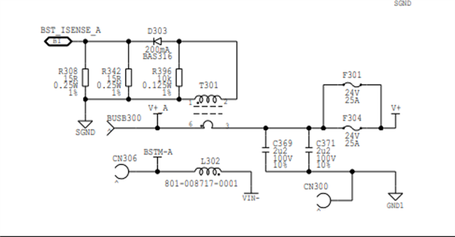
Customer use CT to sample the L current and there will some minus voltage happens, and may above -0.3V.
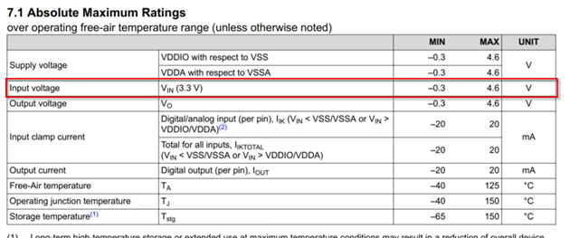
and we have a restrict on -0.3V input voltage.
however, customer told me, there seems more margin for F2803X input voltage. Did we changed some thing for ADC design?
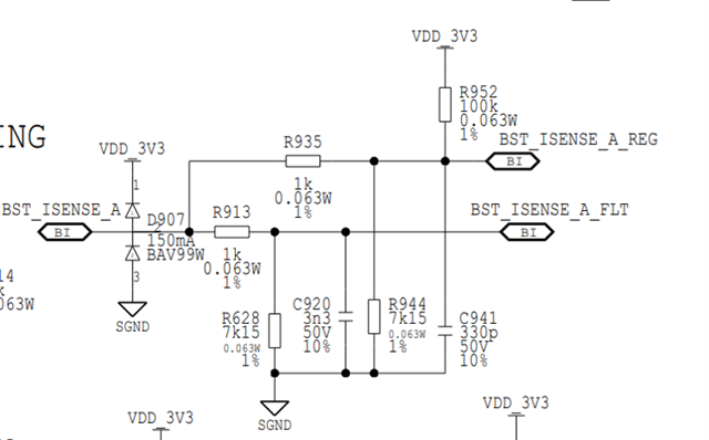
On the other hand, do we have internal clamp diode for ADC pin?
BR
Emma