This thread has been locked.

If you have a related question, please click the "Ask a related question" button in the top right corner. The newly created question will be automatically linked to this question.

TMS320F280049C: Running Instaspin FOC on the F280049C and seeing negative speed feedback

Part Number: TMS320F280049C
Other Parts Discussed in Thread: DRV8353

Hello,
We are using a custom board with Instaspin for F28004xC. For some gains, the motor spins up (unloaded) however the power draw is much higher than expected and the speed feedback shows a large negative number when the setpoint is positive. Is there any documentation on what can cause this? Our board is using 3 low-side shunt resistors for current sensing, and we are using the smart gate driver DRV8353 which has the integrated current sensing gain stage.
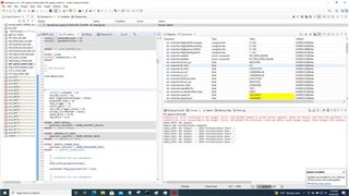
See image before for snip from the debugger, showing negative speed:
Thanks
  • Using lab02 and lab03 to verify the current and voltage sensing circuit on the hardware board, and then using the lab05 to identify the motor parameters.

    If these three labs can't run well on the hardware board, and the identification motor parameters are not correct. You have to check if the current and voltage sensing circuit works well, and the motor can't run well on the other labs.

  • Hi Yanming,
    We are running lab 2 as you suggested. The current sensing is looking correct however, when we perform the voltage offset calculation, the output from the lab is ~0.5 for each phase voltage, compared to the lab example which specifies 1.
    We are operating with a DC bus of 15V, and at 50% voltage measure ~7.5V so a 0.5V offset makes sense, but it is unclear why in the lab for a similar 50% duty-cycle their offset is close to ~1.

    Here is a snip of our outputs before and after the offset calc is performed


  • Hi Yanming in addition to above, we decided to proceed with Lab3 and Lab5 with the following results:

    We progressed through lab3, however when we went to Lab 05 we are seeing an initial current spike that browns out our supply (> 25A). We tried reducing the USER_MOTOR_RES_EST_CURRENT_A and USER_MOTOR_RES_IND_CURRENT_A from 3 and -3 to 0.3 and -0.3 but that had no effect. We saw a similar issue with lab 3, however we resolved this by reducing USER_MOTOR_VOLT_MIN_V and USER_MOTOR_VOLT_MAX_V from 4 and 24 to 0.3 and 2 respectively. Could this be a clue as to what is going on with Lab 5?

    Thanks,

  • That means the current sensing signals are not good. You have to run lab03 and use oscilloscope to check if the waveform captured by a current probe is the same as the sampling value within CCS by using datalog or PWMDAC.

    And then you might try to run the lab04, if the lab04 failed with over current, you have to check if the current sensing circuit works on your hardware board before you try to run the other subsequent labs.

    The following three parameters marked RED in the user.h according to the hardware board.

    //! \brief Defines the maximum voltage at the AD converter

    #define USER_ADC_FULL_SCALE_VOLTAGE_V         ((float32_t)(57.528f))


    //! \brief Defines the maximum current at the AD converter

    #define USER_ADC_FULL_SCALE_CURRENT_A         ((float32_t)(42.843f))


    //! \brief Defines the analog voltage filter pole location, Hz

    #define USER_VOLTAGE_FILTER_POLE_Hz           ((float32_t)(338.357f))


     The sign of the current sensing value marked RED in the hal.h according to the hardware board.

    static inline void

    HAL_readADCDataWithOffsets(HAL_Handle handle, HAL_ADCData_t *pADCData)

    {

        HAL_Obj *obj = (HAL_Obj *)handle;


        float32_t value;


        float32_t current_sf = -HAL_getCurrentScaleFactor(handle);

        float32_t voltage_sf = HAL_getVoltageScaleFactor(handle);

    }

  • Hi thanks for the help, we discovered our issue was we mapped the EPWM#A to the low-side FET and EPWM#B to the high-side FET, once this was swapped we got expected results