Other Parts Discussed in Thread: PCA9536
Hello,
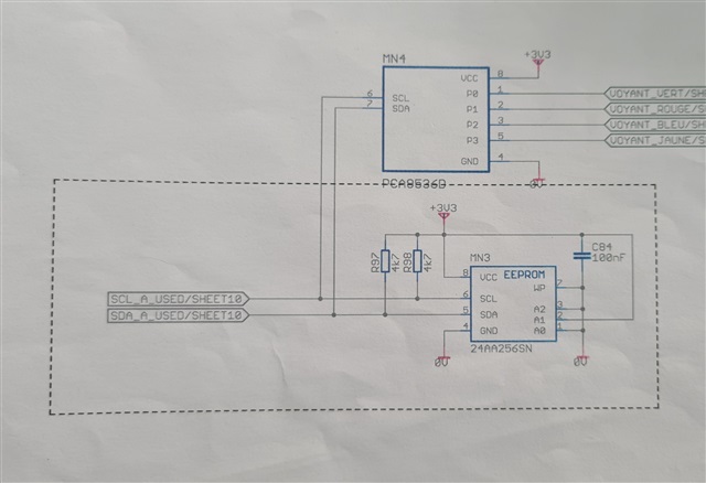
I used I2C bus on my own board with EEPROM 24EE256 and PCA9536 driving by F28069. Address are OK : one is 0x50 (EEPROM) and other 0x41 for PCA.
With EEPROM, everything is ok and works perfectly with the code but IO expander never answers to write or read request.
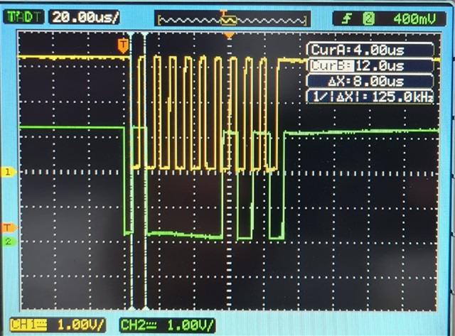
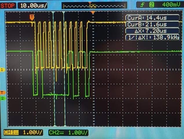
I send a write command every 20 ms. I haven't any errors. I joined scope printscreen and source code.
I use " Uint16 I2C_Write_Data(Uint16 Slave_address, Uint16 Register, Uint16 Data) " such as
I2C_Write_Data(0x41, 0x0001, 0x0000); // every 20 ms
I request to write register 0x1 with 0x0 to the device address 0x41 but at the oscilloscope, I see only address 0x41 and no data ?!? Why ?
Could you please let me know if you have an idea. Thanks for your help
OL
//##################### I2C_Write_Data #################################################################################
// Function Name: void I2C_Write_Data
// Return Type: Uint16
// Arguments: Uint16 Slave_address, Uint16 Register, Uint16 Data
// Description: I2C_Write_Data
//#################################################################################################################
Uint16 I2C_Write_Data(Uint16 Slave_address, Uint16 Register, Uint16 Data)//
{
	Uint16 ii = 0;
	Uint16 TimeOutI2C = 0;

		I2caRegs.I2CMDR.bit.IRS = 1; 				// reset I2C

		__asm(" RPT #10 || NOP");

		// Make sure I2C is not busy and has stopped
		while (I2caRegs.I2CSTR.bit.BB == 1) //;		// busy loop
		{
				TimeOutI2C++;
				if(TimeOutI2C > 20000)
					return 0;
		}
		TimeOutI2C = 0;

		// Clear the SCD bit (stop condition bit)
		I2caRegs.I2CSTR.bit.SCD = 1;				// Clear the SCD bit (stop condition bit)

		while(I2caRegs.I2CMDR.bit.STP == 1) //;		// stop bit loop
		{
				TimeOutI2C++;
				if(TimeOutI2C > 20000)
					return 0;
		}
		TimeOutI2C = 0;

		// code d'origine
		//##################################################
		I2caRegs.I2CSAR = Slave_address;

		//still busy?
		while(I2caRegs.I2CMDR.bit.STP != 0){
			TimeOutI2C++;
			if(TimeOutI2C > 20000)
				return 0;
		}
		TimeOutI2C = 0;

		// Start bit, write mode, Higher 16 address bits, Master, Repeat mode.
		I2caRegs.I2CMDR.bit.TRX = 1; //TRANSMIT_MESSAGE;

		I2caRegs.I2CDXR = Register; // Register

		//##################################################//
		I2caRegs.I2CMDR.all = 0x26A0; //01 00 11 01 01 00 000
		//I2caRegs.I2CMDR.all = 0x27A0; //01 00 11 01 01 00 000
	/*	I2caRegs.I2CMDR.bit.NACKMOD = 0;		// NACK mode bit
		I2caRegs.I2CMDR.bit.FREE 	= 1;		// Stop I2C when suspended
		I2caRegs.I2CMDR.bit.STT 	= 0;		// START condition bit
		I2caRegs.I2CMDR.bit.STP 	= 0;		// STOP condition bit
		I2caRegs.I2CMDR.bit.MST 	= 1;		// Master mode
		I2caRegs.I2CMDR.bit.TRX 	= 1;		// Transmitter mode
		I2caRegs.I2CMDR.bit.XA 		= 0;		// 7-bit addressing mode
		I2caRegs.I2CMDR.bit.RM 		= 1;		// Repeat Mode
		I2caRegs.I2CMDR.bit.DLB 	= 0;		// Digital loopback mode is disabled
		I2caRegs.I2CMDR.bit.IRS 	= 1;		// The I2C module is enabled
		I2caRegs.I2CMDR.bit.STB 	= 0;		// The I2C module is not in the START byte mode
		I2caRegs.I2CMDR.bit.FDF 	= 0;		// Free data format mode is disabled
		I2caRegs.I2CMDR.bit.BC 		= 000;		// 8 bits per data byte
		*/

		//(Lower 16) address bits
		while(I2caRegs.I2CSTR.bit.ARDY != 1){
			TimeOutI2C++;
			if(TimeOutI2C > 20000)
				return 0;
		}
		TimeOutI2C = 0;

		I2caRegs.I2CDXR = Data;  //

		while (I2caRegs.I2CSTR.bit.NACK == 1) // Clear if NACK received
		{
			I2caRegs.I2CSTR.bit.NACK = 1;

			TimeOutI2C++;
			if(TimeOutI2C > 20000)
				return 0;
		}
		TimeOutI2C = 0;

		I2caRegs.I2CMDR.all = 0x0EA0;
	/*	I2caRegs.I2CMDR.bit.NACKMOD = 0;		// NACK mode bit
		I2caRegs.I2CMDR.bit.FREE 	= 1;		// Stop I2C when suspended
		I2caRegs.I2CMDR.bit.STT 	= 0;		// START condition bit
		I2caRegs.I2CMDR.bit.STP 	= 1;		// STOP condition bit
		I2caRegs.I2CMDR.bit.MST 	= 1;		// Master mode
		I2caRegs.I2CMDR.bit.TRX 	= 0;		// Transmitter mode
		I2caRegs.I2CMDR.bit.XA 		= 0;		// 7-bit addressing mode
		I2caRegs.I2CMDR.bit.RM 		= 0;		// Nonrepeat mode
		I2caRegs.I2CMDR.bit.DLB 	= 0;		// Digital loopback mode is disabled
		I2caRegs.I2CMDR.bit.IRS 	= 1;		// The I2C module is enabled
		I2caRegs.I2CMDR.bit.STB 	= 0;		// The I2C module is not in the START byte mode
		I2caRegs.I2CMDR.bit.FDF 	= 0;		// Free data format mode is disabled
		I2caRegs.I2CMDR.bit.BC 		= 000;		// 8 bits per data byte
	*/

		while(I2caRegs.I2CSTR.bit.SCD != 1){
			TimeOutI2C++;
			if(TimeOutI2C > 20000)
				return 0;
		}
		TimeOutI2C = 0;

		I2caRegs.I2CSTR.bit.SCD = 1; // Clear stop condition

		return 1;
	}