Hi,
We are having some trouble with the speed control of our C2000 based custom board. We are using Instaspin MOTION software to control the speed of a BLDC motor, and most of the time the control is fine, but we are experimenting some speed runaways. The conditions in which the speed runaway condition occurs are the following:
- Always in the first run (so initial speed = 0)
- Independent of the reference value
- Speed loop based PI
And the hardware specs are:
- µC: TMS320F28069MPZT
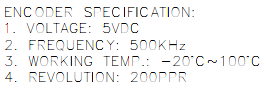
- Encoder:
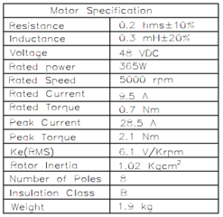
- Motor:
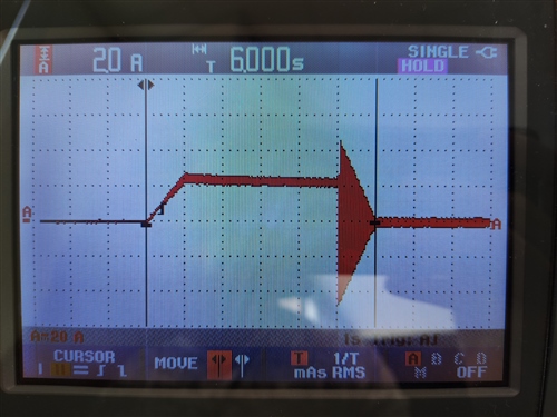
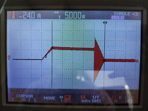
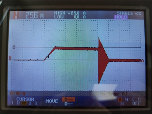
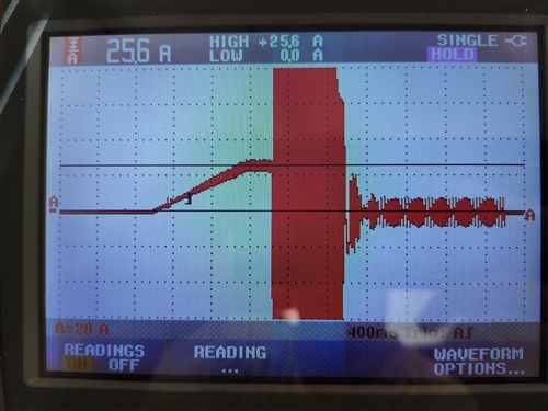
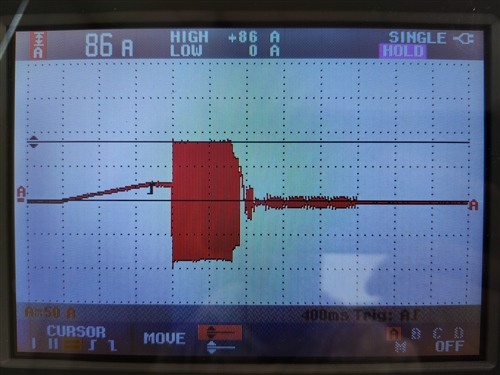
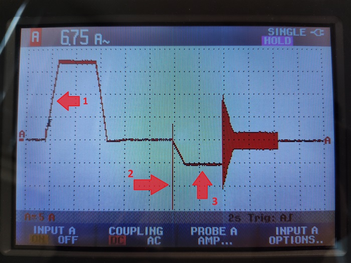
According to the customer, the motor is ignoring the reference value and then spins to the maximum speed of the motor. After that condition, they have to turn the system down in order to get the motor idle status. They ensure that all connections are checked and fine.
All control parameters are tunned accordingly to the Instaspin Labs, and indeed the control is fine excepting those occasionally speed runaways. Because of that we can’t imagine the source of the problem, since as far as we know and according to our measures, the overall status of the system is OK. At TI forums we found this topic, which seems to be the same problem we have, and we can confirm that changing the USER_MOTOR_RES_EST_CURRENT value the problem is mitigating, but not disappearing. According to Lab’s guidelines, we have reached the theoretical “perfect” value of that variable, so we have no improve margin in that way.
May you please confirm that the problem may be related with that variable, and what else can we do to completely solve the problem? The customer is really worried because the system is causing damages at the installation, so we need some 100% sure guidelines to completely avoid this problem.
Thank you very much in advance,
Best regards