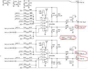
Hi, I'm using TMDSHVMTRPFCKIT with F28335 card to drive a small motor.
When I measured the phase current of the inverter with a external hall sensor or the embedded ADC module, I get the orange waveform but when I measure the same data with oscilloscope connected to the PCB board(connected to the pins ifb-U, ifb-V, etc.) I get the blue graph.

The question is, why are they showing different values(min, max, RMS, etc)?
I already subtracted the offset value and multiplied the gain value(provided in the circuit diagram) to the raw oscilloscope data.

thank you in advance.

