This thread has been locked.

If you have a related question, please click the "Ask a related question" button in the top right corner. The newly created question will be automatically linked to this question.

TMS320F28069F: Instaspin Motorware V16 motor controller issue

Part Number: TMS320F28069F
Other Parts Discussed in Thread: DRV8301, MOTORWARE

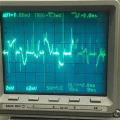
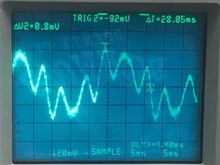
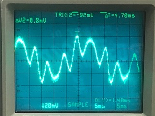
I have a TI Instaspin motorware based project that runs on a custom board using a DRV8301 and TI MOSFETs.  These turn a 24V BLDC motor that is embedded in a water pump. The software was based on motorware v16 proj_lab11a.  The issue is that at a speed just below nominal rated RPM of 3450 the motor spins up out of control.  I added datalog.c to the project so I could plot out angle, current and voltage of the controller to see what's happening.  Here are the waveforms of the motor running just below the nominal speed.

It looks like the current waveform has an oscillation overlaid on it and the angle and voltage look normal.  Should I adjust the gain settings on the current PI loops? And if so how would I go about that.  I've attempted adjustments the gains on both Id and Iq based on what I've read in the Instaspin Lab manual but haven't had any luck making improvements.

Thanks in advance

  • Do you run motor parameters identification on the customer's board? And have the same identified parameters as on the TI Hardware Kit? If not, that means you have to tune/fix  the current/voltage sensing circuit first, and check if the hardware parameters are set correctly in user.h.

    Did you have more testing current waveforms capture by an oscilloscope with current probe at different speed?

  • I haven't run motor identification myself.  I assumed that my predecessor had done that already as a custom motor is identified in user.h and its parameters are fully populated.  But it sounds like you are suggesting that I should rerun the identification process and verify that.  Can I run identification using the custom board or do I need to get a TI Hardware Kit to do that?

    As for your second question, I've run the motor at different speeds and observed the datalog waveforms.  The oscillation on top of the current sin wave is always there to some degree regardless of speed.  Its frequency seems to be 6 times that of the current sin wave and its amplitude increases as the current sin wave increases.  I believe the 6 times correlates to the PWM frequency.

    I don't have a current probe for my scope so I did a few differential measurements across the shunt resistor of the output.

    Current at Nominal speed

    Current at slow speed (approx 1/3 nominal)

    Current during runaway condition

  • Not sure if this is helpful, but I used datalog to plot angle, current and gMotorVars.Iq_A below

  • Can I run identification using the custom board or do I need to get a TI Hardware Kit to do that?

    Do the identification on both customer's board and TI hardware kit, and compare the identified value. If there are significant error between both kits, that means you have to optimize the current and voltage sensing circuit on the customer's board.

    What reference speed are you setting to run the motor? A positive value or a negative value? Can you post the spec. of the motor?

    It's better to measure some current at different speed with current probe. It's difficult to analysis and solve the issue if there is not enough information.

  • I'll start working on the ID process today.  I have the HW kit on its way.  There is a speed pot on the custom board to set the speed.  It ranges from around 800 to 3600 rpm. I set the gMotorVars.SpeedRef_krpm to a negative number to get the motor to spin in the correct direction.

    I will look into getting a current probe.

    I appreciate the help and have no issue providing whatever info you need to assist me.  As I've mentioned in other posts, I inherited this application and I'm not a motor control expert.  This is a learning process for me which I actually enjoy.  Thanks so much for the help.

    Here are the motor parameters from user.h

    #elif (USER_MOTOR == Short24v)
    #define USER_MOTOR_TYPE MOTOR_Type_Pm
    #define USER_MOTOR_NUM_POLE_PAIRS (4)
    #define USER_MOTOR_Rr (NULL)
    //#define USER_MOTOR_Rs (NULL)
    //#define USER_MOTOR_Ls_d (NULL)
    //#define USER_MOTOR_Ls_q (NULL)
    //#define USER_MOTOR_RATED_FLUX (NULL)
    #define USER_MOTOR_Rs (0.2459702)//(0.3826179)//(0.2489702)
    #define USER_MOTOR_Ls_d (0.0004539846)
    #define USER_MOTOR_Ls_q (0.0004539846)
    #define USER_MOTOR_RATED_FLUX (0.0617828)//(0.2390623)//(0.215354)
    #define USER_MOTOR_MAGNETIZING_CURRENT (NULL)
    #define USER_MOTOR_RES_EST_CURRENT (2.0)//(1.0)//(2.5)//
    #define USER_MOTOR_IND_EST_CURRENT (-1.5)//(-0.5)
    #define USER_MOTOR_MAX_CURRENT (15.0)//(10.0)//(20.0)
    #define USER_MOTOR_FLUX_EST_FREQ_Hz (150.0)//(100.0)//(20.0)
    #define IPD_HFI_EXC_FREQ_HZ (750.0) // excitation frequency, Hz
    #define IPD_HFI_LP_SPD_FILT_HZ (10.0) // lowpass filter cutoff frequency, Hz
    #define IPD_HFI_HP_IQ_FILT_HZ (20.0) // highpass filter cutoff frequency, Hz
    #define IPD_HFI_KSPD (31.4) // the speed gain value
    #define IPD_HFI_EXC_MAG_COARSE_PU (0.2) // coarse IPD excitation magnitude, pu
    #define IPD_HFI_EXC_MAG_FINE_PU (0.2) // fine IPD excitation magnitude, pu
    #define IPD_HFI_EXC_TIME_COARSE_S (0.2) // coarse wait time, sec max 0.64
    #define IPD_HFI_EXC_TIME_FINE_S (0.1) // fine wait time, sec max 0.4
    #define AFSEL_FREQ_HIGH_PU (_IQ(20.0 / USER_IQ_FULL_SCALE_FREQ_Hz))
    #define AFSEL_FREQ_LOW_PU (_IQ(10.0 / USER_IQ_FULL_SCALE_FREQ_Hz))
    #define AFSEL_IQ_SLOPE_EST (_IQ((float)(1.0/0.1/USER_ISR_FREQ_Hz)))
    #define AFSEL_IQ_SLOPE_HFI (_IQ((float)(1.0/1.0/USER_ISR_FREQ_Hz)))
    #define AFSEL_IQ_SLOPE_THROTTLE_DWN (_IQ((float)(1.0/0.05/USER_ISR_FREQ_Hz)))
    #define AFSEL_MAX_IQ_REF_EST (_IQ(0.4))
    #define AFSEL_MAX_IQ_REF_HFI (_IQ(0.4))
    #define USER_MAX_NEGATIVE_ID_REF_CURRENT_A (-0.5 * USER_MOTOR_MAX_CURRENT)

  • Any comparison results on your own board?

    The issue is that at a speed just below nominal rated RPM of 3450 the motor spins up out of control. 

    What do you mean this? Do you try to increase the dc bus voltage to see what happens when run the motor at high speed? 

  • Sorry no comparison yet.  Just got the TI Hardware Kit today.  Bare with me as I figure that out.

    Regarding your 2nd question, just shy of 3200 rpm the motor speed takes off as fast as it can go. When spinning out of control the board will eventually trip out on over current.

    If I increase the dc bus voltage it is able to stay in control for higher rpm but still not able to stay in control all the way to max speed though.

    By the way, I have a current probe on order.

  • You mean the motor runs well at low speed, like 3200rpm, it only has the issue at high speed.

    What USER_MAX_VS_MAG_PU is set in user.h? Please check if gMotorVars.Vs is close to USER_MAX_VS_MAG_PU. If yes, you have to increase the dc bus voltage, or implement field weakening control as lab09 for high speed.

  • When I ran proj_lab02a using the TI Hardware Kit I got these motor parameters.  FYI I ran it 3 times so there are 3 numbers each

    .Rs_Ohm = 0.265949309, 0.257745683, 0.250531137

    Ls_d & Ls_q = 0.0, 2.56935112e-10, 2.56935112e-10

    RATED_FLUX = 0.00514337141, 0.0128469346, 0.0302353743

    From the user.h for my custom project

    #define USER_MOTOR_Rs (0.2459702)
    #define USER_MOTOR_Ls_d (0.0004539846)
    #define USER_MOTOR_Ls_q (0.0004539846)
    #define USER_MOTOR_RATED_FLUX (0.0617828)

  • Correct, it only has the issue as high speed.  But you can see the oscillation on the current sin wave at all speeds.

    USER_MAX_VS_MAG_PU = 2/3 and Vs never gets over 0.2

  • I got the current probe for the scope today, here is a trace of one of the phases.  This is at a speed of 1250rpm which is about 1/3 nominal speed.

    I can measure a fundamental current sin wave that is 28ms.

    But then there is an oscillation on top of the sin wave that is about 6 times faster

  • You might try to identify the motor using lab02c since the motor is a low inductance one.

    It seems like the motor was not identified properly. Please don't add any load on the motor for identification, and set the correct identification variables value in user.h file according to the specification of the motor, to make sure the motor spin smoothly during Flux measurement and Ls identification states.


    #define USER_MOTOR_RES_EST_CURRENT     (1.0)                               // A - 10-30% of rated current of the motor

    #define USER_MOTOR_IND_EST_CURRENT     (-1.0)                             // A - 10-30% of rated current of the motor, just enough to enable rotation

    #define USER_MOTOR_MAX_CURRENT           (5.0)                               // A - 30~150% of rated current of the motor

    #define USER_MOTOR_FLUX_EST_FREQ_Hz     (20.0)                           // Hz - 10~30% rated frequency of the motor

  • Yanming

    I ran lab02c several dozen times starting at a PWM of 45kHz and working my way up to 75kHz looking for consistent results.  I also varied the USER_MOTOR_FLUX_FREQ_Hz from 20 to 70 to see if that would help.  Here is a table of the frequencies that worked the best.

  • Which kit are you using? You might set the PWM and ISR frequencies as below in user.h file. And tune the identification parameters as mentioned above. The USER_MOTOR_IND_EST_CURRENT and USER_MOTOR_MAX_CURRENT need to set a right value according to the spec. of the motor. Don't add load on the motor for identification.

    #define USER_PWM_FREQ_kHz                (45.0)

    #define USER_NUM_PWM_TICKS_PER_ISR_TICK        (3)

  • The TI kit is an older DRV8301-HC-EVM Rev D with a F2806x ISO controlCard Rel 0.4 plugged into it.  The pump is attached to the motor as it is embedded inside the pump.  However, it is not sitting in water so there should be no load on it.

    Using your recommended user settings here are the ID results.  The numbers at the top are the averages of the 10 results.  Note there was one attempt that errored out and those results are not included.

    Here are the motor parameters from user.h

    #elif (USER_MOTOR == JR_Motor)
    #define USER_MOTOR_TYPE MOTOR_Type_Pm
    #define USER_MOTOR_NUM_POLE_PAIRS (4)
    #define USER_MOTOR_Rr (NULL)
    #define USER_MOTOR_Rs (NULL)
    #define USER_MOTOR_Ls_d (NULL)
    #define USER_MOTOR_Ls_q (NULL)
    #define USER_MOTOR_RATED_FLUX (NULL)
    #define USER_MOTOR_MAGNETIZING_CURRENT (NULL)
    #define USER_MOTOR_RES_EST_CURRENT (1.0)
    #define USER_MOTOR_IND_EST_CURRENT (-1.0)
    #define USER_MOTOR_MAX_CURRENT (5.0)
    #define USER_MOTOR_FLUX_EST_FREQ_Hz (20.0)
    #define USER_MOTOR_FREQ_LOW (6.0) // Hz - suggested to set to 10% of rated motor frequency
    #define USER_MOTOR_FREQ_HIGH (60.0) // Hz - suggested to set to 100% of rated motor frequency
    #define USER_MOTOR_FREQ_MAX (72.0) // Hz - suggested to set to 120% of rated motor frequency
    #define USER_MOTOR_VOLT_MIN (3.0) // Volt - suggested to set to 15% of rated motor voltage
    #define USER_MOTOR_VOLT_MAX (24.0) // Volt - suggested to set to 100% of rated motor voltage

  • At a PWM of 45kHz, if I use anything close to these inductive parameters the project will error with cntrlFreq_Low.  With an Rs of 0.25, Lsd & Lsq need to be above 5.555e-6.

  • It seems like the motor parameters are not identified correctly since the inductance is too small in most cases. I guess the motor didn't run during Ls identification. You have to tune the identification variables as mentioned above, to make sure that the motor runs smoothly during the Flux and Ls identification process.

  • When you say adjust identification variables I assume you mean these.

    #define USER_MOTOR_RES_EST_CURRENT     (1.0)                               // A - 10-30% of rated current of the motor

    #define USER_MOTOR_IND_EST_CURRENT     (-1.0)                             // A - 10-30% of rated current of the motor, just enough to enable rotation

    #define USER_MOTOR_MAX_CURRENT           (5.0)                               // A - 30~150% of rated current of the motor

    #define USER_MOTOR_FLUX_EST_FREQ_Hz     (20.0)                           // Hz - 10~30% rated frequency of the motor

    I've adjusted these up and down in many combinations.  I can get the motor to run smoothly but when it does  I get the very low (close to zero) results for inductance.  I've also following the instruction in the Instaspin Lab manual on page 72, however those haven't improved the results.

    I've tried a lot of the things mention in the manual below and also adjust variables according to comments in the code.  However, the ID process either fails during the inductive part or the test or the results are way too low to be useful.

    Regarding the load.  The motor is embedded inside a pump housing.  I have the assembly free standing and not in water, so there is no back pressure. However does the inertia of the pump mechanism still count as a load?  Should I see if the motor can be removed and run naked?

  • Yes, these parameters in user.h. Did you have any clear current waveforms to show the identification process? It seems like the motor didn't run smoothly, the identified inductance is not correct. What's the rated current, power and speed of this motor?

  • I can get the motor to run smoothly.  At least I assume so as there is no humming or jerking of the pump casing.  The nominal specs  of the motor are 24vdc, 5 amps, 120W.  Max speed rating is 3450 rpm.  I will try and upload a video of the current waveform.

    I sent you a link to a video of the current waveform during the ID process.  It was too big to post here.

  • The identified Flux and Ls should be similar every times if the motor runs well.

    You might try to download the latest motorWare and use the original lab02c to identify the motor again since you are using TI hardware kit, just change the identification variables as mentioned above.

    http://www.ti.com/tool/c2000ware

  • All the ID processes I've been running, and all the results I've shared with you are from using the latest motorware version 18.

    I'm working on getting a bare motor that is not embedded in the pump housing and see if that will help with getting consistent ID results.

  • Agree with you. You might try to identify and run a generic motor first to verify the hardware kit and software. Only the data of group 3 and 10 you mentioned above seems reasonable, but the differences between these two groups are too large, the differences between every identification parameters should be less than 10% in most cases if the motor and hardware are good, no more than 20% in a worse case.

  • I finally received a bare motor and after having to adjust lots of parameters I got the ID process to run consistently.  Here are the results.

    Here are the motor parameters I used.

    #define USER_MOTOR_TYPE MOTOR_Type_Pm
    #define USER_MOTOR_NUM_POLE_PAIRS (2)
    #define USER_MOTOR_Rr (NULL)
    #define USER_MOTOR_Rs (NULL)
    #define USER_MOTOR_Ls_d (NULL)
    #define USER_MOTOR_Ls_q (NULL)
    #define USER_MOTOR_RATED_FLUX (NULL)
    #define USER_MOTOR_MAGNETIZING_CURRENT (NULL)
    #define USER_MOTOR_RES_EST_CURRENT (3.0) // A - 10-30% of rated current of the motor (Yanming)
    #define USER_MOTOR_IND_EST_CURRENT (-3.0) // A - 10-30% of rated current of the motor, just enough to enable rotation (Yanming)
    #define USER_MOTOR_MAX_CURRENT (8.0) // A - 30~150% of rated current of the motor (Yanming)
    #define USER_MOTOR_FLUX_EST_FREQ_Hz (12.0) // Hz - 10~30% rated frequency of the motor (Yanming)
    #define USER_MOTOR_FREQ_LOW (6.0) // Hz - suggested to set to 10% of rated motor frequency
    #define USER_MOTOR_FREQ_HIGH (60.0) // Hz - suggested to set to 100% of rated motor frequency
    #define USER_MOTOR_FREQ_MAX (75.0) // Hz - suggested to set to 120% of rated motor frequency
    #define USER_MOTOR_VOLT_MIN (8.0) // Volt - suggested to set to 15% of rated motor voltage
    #define USER_MOTOR_VOLT_MAX (28.0) // Volt - suggested to set to 100% of rated motor voltage

    The interesting thing is I noticed the same jagged current waveform during the ID process as I posted above using my custom board and software.

    USER_MOTOR_FLUX_EST_FREQ_Hz     (20.0)

    USER_MOTOR_FLUX_EST_FREQ_Hz     (40.0)

    As you can see there is the main commutation sin wave that rotates the motor, but then there is a smaller amplitude sin wave at a higher frequency riding on top of that.  It is consistently 5 times (not 6 as I stated above) the motor commutation frequency regardless of motor speed. 

    Is this something caused by the motor itself?  My concern is that this is what is causing loss of speed control at higher RPM.  I also believe it is causing the FAST Estimator to report incorrect motor speed.  Using the current probe I can measure how fast the motor is turning and gMotorVars.Speed_krpm is higher by 30-60% depending on speed.

  • What current waveform do you monitor if running the motor with TI hardware kit? Are there any significant difference between the identification motor parameters by using your custom board and TI hardware kit?

    It seems like the current or voltage sensing signals on your custom board are not good for InstaSPIN-FOC.

  • The two pictures in my previous post are from one of the motor phases while using the TI hardware kit during identification.

    These are the motor parameters my predecessor was using on the custom board.  LS is not too far off, but Rated Flux is almost an order of magnitude.

    #elif (USER_MOTOR == Short24v)
    #define USER_MOTOR_TYPE MOTOR_Type_Pm
    #define USER_MOTOR_NUM_POLE_PAIRS (4)
    #define USER_MOTOR_Rr (NULL)
    //#define USER_MOTOR_Rs (NULL)
    //#define USER_MOTOR_Ls_d (NULL)
    //#define USER_MOTOR_Ls_q (NULL)
    //#define USER_MOTOR_RATED_FLUX (NULL)
    #define USER_MOTOR_Rs (0.2459702)//(0.3826179)//(0.2489702)
    #define USER_MOTOR_Ls_d (0.0004539846)
    #define USER_MOTOR_Ls_q (0.0004539846)
    #define USER_MOTOR_RATED_FLUX (0.0617828)//(0.2390623)//(0.215354)
    #define USER_MOTOR_MAGNETIZING_CURRENT (NULL)
    #define USER_MOTOR_RES_EST_CURRENT (2.0)//(1.0)//(2.5)//
    #define USER_MOTOR_IND_EST_CURRENT (-1.5)//(-0.5)
    #define USER_MOTOR_MAX_CURRENT (15.0)//(10.0)//(20.0)
    #define USER_MOTOR_FLUX_EST_FREQ_Hz (150.0)//(100.0)//(20.0)
    #define IPD_HFI_EXC_FREQ_HZ (750.0) // excitation frequency, Hz
    #define IPD_HFI_LP_SPD_FILT_HZ (10.0) // lowpass filter cutoff frequency, Hz
    #define IPD_HFI_HP_IQ_FILT_HZ (20.0) // highpass filter cutoff frequency, Hz
    #define IPD_HFI_KSPD (31.4) // the speed gain value
    #define IPD_HFI_EXC_MAG_COARSE_PU (0.2) // coarse IPD excitation magnitude, pu
    #define IPD_HFI_EXC_MAG_FINE_PU (0.2) // fine IPD excitation magnitude, pu
    #define IPD_HFI_EXC_TIME_COARSE_S (0.2) // coarse wait time, sec max 0.64
    #define IPD_HFI_EXC_TIME_FINE_S (0.1) // fine wait time, sec max 0.4
    #define AFSEL_FREQ_HIGH_PU (_IQ(20.0 / USER_IQ_FULL_SCALE_FREQ_Hz))
    #define AFSEL_FREQ_LOW_PU (_IQ(10.0 / USER_IQ_FULL_SCALE_FREQ_Hz))
    #define AFSEL_IQ_SLOPE_EST (_IQ((float)(1.0/0.1/USER_ISR_FREQ_Hz)))
    #define AFSEL_IQ_SLOPE_HFI (_IQ((float)(1.0/1.0/USER_ISR_FREQ_Hz)))
    #define AFSEL_IQ_SLOPE_THROTTLE_DWN (_IQ((float)(1.0/0.05/USER_ISR_FREQ_Hz)))
    #define AFSEL_MAX_IQ_REF_EST (_IQ(0.4))
    #define AFSEL_MAX_IQ_REF_HFI (_IQ(0.4))
    #define USER_MAX_NEGATIVE_ID_REF_CURRENT_A (-0.5 * USER_MOTOR_MAX_CURRENT)

    I'm getting a similar current waveform on both the TI Hardware Kit and the custom board.  The custom board is very similar in design to the HW Kit.

  • Any load and speed the motor is running at? Do you try to run the other motor with a load at a higher speed?

  • During ID process I was using a bare motor as discussed previously so there was no load on the motor.  During the ID process I used 12Hz which is 20% of its rated frequency of 60Hz and should be around 700rpm.

    The other motor is embedded in a casing with a water pump and is loaded. When I run it at higher speeds it will eventually run out of controller and trip out on over current..  

  • So as I look closer at this waveform and how consistent it is regardless of speed and load it makes me believe that it is coming from the motor.  If you measure where each small dip/peak is over the larger commutation waveform (for a given phase) they approximately coincide with the pole crossing points of the other two phases.

    Are these caused by inductive coupling between the phases, back emf or some other characteristic of the this PMSM motor?


  • You might try to run the other PMSM motor if possible, and see what current waveform? Maybe, the BEMF share of your current motor is sinusoidal.

    Or you can try to increase the identification frequency, it seems like 12Hz is too low.

    And then you use lab05b or lab10a to run the motor with the identification parameters, and try to add some load to see what happens.