Part Number: TMS320F280049C
Dear team:
During the PWM frequency conversion and phase shift control test, my customer found that when the PWM is configured as follows.
PWM2: UP_DOWN mode, SET when ZERO, CLR when PRD, 50% duty cycle output with dead band. Send synchronization signal when CTR = 0;
PWM3: UP_DOWN mode, SET when ZERO, CLR when PRD, 50% duty cycle output with dead band. PWM3 is phase shifted relative to PWM2, and the phase shift value is fixed in the range of Phase = PRD * 0.98.
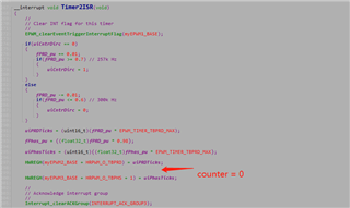
Timer2 generates 100k frequency interrupt. Change the PRD value according to the fixed step in the interrupt, and calculate the new phase shift value accordingly to ensure that the phases of PWM3 and PWM2 remain unchanged.
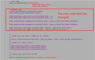
Enable Global Load function:
PWM2: PRD is loaded into active by shadow at the ZERO point
PWM3: PRD is loaded into active by shadow at the synchronization signal input point
Question:
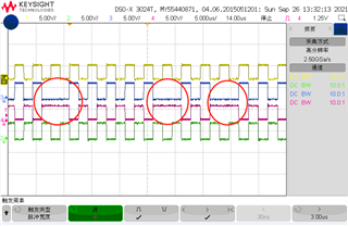
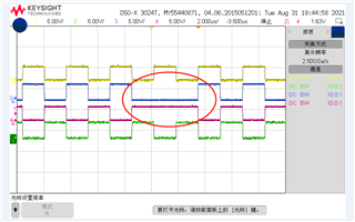
During the test, pwm3 will have the probability that pwm3a is all high and pwm3b is all low in one cycle.
In order to facilitate verification, the customer has modified the official routine. You can completely replace this part of the code with epwm_ex3_synchronization.c in the routine to reproduce this problem.
//#############################################################################
//
// FILE: epwm_ex3_synchronization.c
//
// TITLE: ePWM Using The Synch Chain and Phase Shift.
//
//! \addtogroup driver_example_list
//! <h1>ePWM Synchronization</h1>
//!
//! This example configures ePWM1, ePWM2, ePWM3 and ePWM4 as follows
//! - ePWM1 without phase shift as master
//! - ePWM2 with phase shift of 300 TBCLKs
//! - ePWM3 with phase shift of 600 TBCLKs
//! - ePWM4 with phase shift of 900 TBCLKs
//!
//! \b External \b Connections \n
//! - GPIO0 EPWM1A
//! - GPIO1 EPWM1B
//! - GPIO2 EPWM2A
//! - GPIO3 EPWM2B
//! - GPIO4 EPWM3A
//! - GPIO5 EPWM3B
//! - GPIO6 EPWM4A
//! - GPIO7 EPWM4B
//!
//! \b Watch \b Variables \n
//! - None.
//
//#############################################################################
// $TI Release: F28004x Support Library v1.12.00.00 $
// $Release Date: Fri Feb 12 18:57:27 IST 2021 $
// $Copyright:
// Copyright (C) 2021 Texas Instruments Incorporated - http://www.ti.com/
//
// Redistribution and use in source and binary forms, with or without
// modification, are permitted provided that the following conditions
// are met:
//
// Redistributions of source code must retain the above copyright
// notice, this list of conditions and the following disclaimer.
//
// Redistributions in binary form must reproduce the above copyright
// notice, this list of conditions and the following disclaimer in the
// documentation and/or other materials provided with the
// distribution.
//
// Neither the name of Texas Instruments Incorporated nor the names of
// its contributors may be used to endorse or promote products derived
// from this software without specific prior written permission.
//
// THIS SOFTWARE IS PROVIDED BY THE COPYRIGHT HOLDERS AND CONTRIBUTORS
// "AS IS" AND ANY EXPRESS OR IMPLIED WARRANTIES, INCLUDING, BUT NOT
// LIMITED TO, THE IMPLIED WARRANTIES OF MERCHANTABILITY AND FITNESS FOR
// A PARTICULAR PURPOSE ARE DISCLAIMED. IN NO EVENT SHALL THE COPYRIGHT
// OWNER OR CONTRIBUTORS BE LIABLE FOR ANY DIRECT, INDIRECT, INCIDENTAL,
// SPECIAL, EXEMPLARY, OR CONSEQUENTIAL DAMAGES (INCLUDING, BUT NOT
// LIMITED TO, PROCUREMENT OF SUBSTITUTE GOODS OR SERVICES; LOSS OF USE,
// DATA, OR PROFITS; OR BUSINESS INTERRUPTION) HOWEVER CAUSED AND ON ANY
// THEORY OF LIABILITY, WHETHER IN CONTRACT, STRICT LIABILITY, OR TORT
// (INCLUDING NEGLIGENCE OR OTHERWISE) ARISING IN ANY WAY OUT OF THE USE
// OF THIS SOFTWARE, EVEN IF ADVISED OF THE POSSIBILITY OF SUCH DAMAGE.
// $
//#############################################################################
//
// Included Files
//
#include "driverlib.h"
#include "device.h"
#include "board.h"
#define EPWM_TIMER_TBPRD_MAX ((float32_t)277.0) // 180kHz
//
// Function Prototypes
//
void initEPWM(uint32_t base);
__interrupt void Timer2ISR(void);
__interrupt void epwm2ISR(void);
__interrupt void epwm3ISR(void);
__interrupt void epwm4ISR(void);
//
// Main
//
void main(void)
{
//
// Initialize device clock and peripherals
//
Device_init();
//
// Disable pin locks and enable internal pull ups.
//
Device_initGPIO();
//
// Initialize PIE and clear PIE registers. Disables CPU interrupts.
//
Interrupt_initModule();
//
// Initialize the PIE vector table with pointers to the shell Interrupt
// Service Routines (ISR).
//
Interrupt_initVectorTable();
//
// Assign the interrupt service routines to ePWM interrupts
//
//Interrupt_register(INT_EPWM1, &epwm1ISR);
//Interrupt_register(INT_EPWM2, &epwm2ISR);
//Interrupt_register(INT_EPWM3, &epwm3ISR);
//Interrupt_register(INT_EPWM4, &epwm4ISR);
// add Timer Interrupt
Interrupt_register(INT_TIMER2, &Timer2ISR);
// Initialize timer period to maximum
CPUTimer_setPeriod(CPUTIMER2_BASE, DEVICE_SYSCLK_FREQ/100000 ); // 100KHz
// Initialize pre-scale counter to divide by 1 (SYSCLKOUT)
CPUTimer_setPreScaler(CPUTIMER2_BASE, 0);
// Make sure timer is stopped
CPUTimer_stopTimer(CPUTIMER2_BASE);
CPUTimer_setEmulationMode(CPUTIMER2_BASE,
CPUTIMER_EMULATIONMODE_STOPAFTERNEXTDECREMENT);
// Reload all counter register with period value
CPUTimer_reloadTimerCounter(CPUTIMER2_BASE);
// Restart timer
CPUTimer_resumeTimer(CPUTIMER2_BASE);
//
// Configure GPIO0/1 , GPIO2/3 and GPIO4/5 and GPIO6/7 as
// ePWM1A/1B, ePWM2A/2B, ePWM3A/3B, ePWM4A/4B pins respectively
//
Board_init();
// Disable sync(Freeze clock to PWM as well). GTBCLKSYNC is applicable
// only for multiple core devices. Uncomment the below statement if
// applicable.
//
// SysCtl_disablePeripheral(SYSCTL_PERIPH_CLK_GTBCLKSYNC);
SysCtl_disablePeripheral(SYSCTL_PERIPH_CLK_TBCLKSYNC);
//
// Initialize PWM1 without phase shift as master
//
//initEPWM(myEPWM1_BASE);
//
// Initialize PWM2 with phase shift of 300 TBCLKs
//
initEPWM(myEPWM2_BASE);
//
// Initialize PWM3 with phase shift of 600 TBCLKs
//
initEPWM(myEPWM3_BASE);
EPWM_enablePhaseShiftLoad(myEPWM3_BASE);
EPWM_setPhaseShift(myEPWM3_BASE, 274);
EPWM_setDeadBandOutputSwapMode(myEPWM3_BASE, EPWM_DB_OUTPUT_A, 1);
EPWM_setDeadBandOutputSwapMode(myEPWM3_BASE, EPWM_DB_OUTPUT_B, 1);
//
// Initialize PWM4 with phase shift of 900 TBCLKs
//
//initEPWM(myEPWM4_BASE);
//EPWM_selectPeriodLoadEvent(myEPWM4_BASE, EPWM_SHADOW_LOAD_MODE_SYNC);
//EPWM_setPhaseShift(myEPWM4_BASE, 900);
//EPWM_setTimeBaseCounter(myEPWM4_BASE, 900);
//
// ePWM1 SYNCO is generated on CTR=0//
//
//EPWM_setSyncOutPulseMode(EPWM1_BASE, EPWM_SYNC_OUT_PULSE_ON_COUNTER_ZERO);
//
// ePWM2 uses the ePWM 1 SYNCO as its SYNCIN.
// ePWM2 SYNCO is generated from its SYNCIN, which is ePWM1 SYNCO
//
EPWM_setSyncOutPulseMode(myEPWM2_BASE, EPWM_SYNC_OUT_PULSE_ON_COUNTER_ZERO);
EPWM_setSyncOutPulseMode(myEPWM3_BASE, EPWM_SYNC_OUT_PULSE_DISABLED);
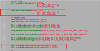
// PWM LINK
EPWM_setupEPWMLinks(myEPWM3_BASE,
EPWM_LINK_WITH_EPWM_2,
EPWM_LINK_TBPRD);
// Global Load
EPWM_enableGlobalLoad(myEPWM2_BASE);
EPWM_enableGlobalLoad(myEPWM3_BASE);
EPWM_setGlobalLoadEventPrescale(myEPWM2_BASE, 1);
EPWM_setGlobalLoadEventPrescale(myEPWM3_BASE, 1);
EPWM_enableGlobalLoadRegisters(myEPWM2_BASE, EPWM_GL_REGISTER_TBPRD_TBPRDHR);
EPWM_enableGlobalLoadRegisters(myEPWM3_BASE, EPWM_GL_REGISTER_TBPRD_TBPRDHR);
EPWM_setGlobalLoadTrigger(myEPWM2_BASE, EPWM_GL_LOAD_PULSE_CNTR_ZERO);
EPWM_setGlobalLoadTrigger(myEPWM3_BASE, EPWM_GL_LOAD_PULSE_SYNC);
//
// ePWM4 uses the ePWM 1 SYNCO as its SYNCIN.
//
//SysCtl_setSyncInputConfig(SYSCTL_SYNC_IN_EPWM4, SYSCTL_SYNC_IN_SRC_EPWM1SYNCOUT);
//
// Enable all phase shifts.
//
//EPWM_enablePhaseShiftLoad(myEPWM2_BASE);
//EPWM_enablePhaseShiftLoad(myEPWM3_BASE);
//EPWM_enablePhaseShiftLoad(myEPWM4_BASE);
//
// Enable sync and clock to PWM
//
SysCtl_enablePeripheral(SYSCTL_PERIPH_CLK_TBCLKSYNC);
//
// Enable ePWM interrupts
//
//Interrupt_enable(INT_EPWM1);
//Interrupt_enable(INT_EPWM2);
//Interrupt_enable(INT_EPWM3);
//Interrupt_enable(INT_EPWM4);
Interrupt_enable(INT_TIMER2);
CPUTimer_enableInterrupt(CPUTIMER2_BASE);
//
// Enable Global Interrupt (INTM) and realtime interrupt (DBGM)
//
EINT;
ERTM;
//
// IDLE loop. Just sit and loop forever (optional):
//
for(;;)
{
}
}
//
// epwm1ISR - ePWM 1 ISR
//
uint16_t uiCntrDirc = 0;
uint16_t uiPRDTicks = 0;
uint16_t uiPhasTicks = 0;
float32_t fPRD_pu = 0.6;
float32_t fPhas_pu = 0.0;
__interrupt void Timer2ISR(void)
{
//
// Clear INT flag for this timer
//
EPWM_clearEventTriggerInterruptFlag(myEPWM1_BASE);
if(uiCntrDirc == 0)
{
fPRD_pu += 0.01;
if(fPRD_pu >= 0.7) // 257k Hz
{
uiCntrDirc = 1;
}
}
else
{
fPRD_pu -= 0.01;
if(fPRD_pu <= 0.6) // 300k Hz
{
uiCntrDirc = 0;
}
}
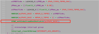
uiPRDTicks = (uint16_t)(fPRD_pu * EPWM_TIMER_TBPRD_MAX);
fPhas_pu = ((float32_t)fPRD_pu * 0.98);
uiPhasTicks = (uint16_t)((float32_t)fPhas_pu * EPWM_TIMER_TBPRD_MAX);
HWREGH(myEPWM2_BASE + HRPWM_O_TBPRD) = uiPRDTicks;
HWREGH(myEPWM3_BASE + HRPWM_O_TBPHS + 1) = uiPhasTicks;
//
// Acknowledge interrupt group
//
Interrupt_clearACKGroup(INTERRUPT_ACK_GROUP3);
}
//
// epwm2ISR - ePWM 2 ISR
//
__interrupt void epwm2ISR(void)
{
//
// Clear INT flag for this timer
//
EPWM_clearEventTriggerInterruptFlag(myEPWM2_BASE);
//
// Acknowledge interrupt group
//
Interrupt_clearACKGroup(INTERRUPT_ACK_GROUP3);
//GLDMODE = 0xF gfrcld
//EPWM_forceGlobalLoadOneShotEvent(myEPWM2_BASE);
//GLDMODE = 0x3 syncevt
//EPWM_setGlobalLoadOneShotLatch(myEPWM2_BASE);
}
//
// epwm3ISR - ePWM 3 ISR
//
__interrupt void epwm3ISR(void)
{
//
// Clear INT flag for this timer
//
EPWM_clearEventTriggerInterruptFlag(myEPWM3_BASE);
//
// Acknowledge interrupt group
//
Interrupt_clearACKGroup(INTERRUPT_ACK_GROUP3);
}
//
// epwm4ISR - ePWM 4 ISR
//
__interrupt void epwm4ISR(void)
{
//
// Clear INT flag for this timer
//
EPWM_clearEventTriggerInterruptFlag(myEPWM4_BASE);
//
// Acknowledge interrupt group
//
Interrupt_clearACKGroup(INTERRUPT_ACK_GROUP3);
}
void initEPWM(uint32_t base)
{
//
// Set-up TBCLK
//
EPWM_setTimeBasePeriod(base, EPWM_TIMER_TBPRD_MAX);
EPWM_setPhaseShift(base, 0U);
EPWM_setTimeBaseCounter(base, 0U);
//
// Set Compare values
//
//EPWM_setCounterCompareValue(base,
// EPWM_COUNTER_COMPARE_A,
// EPWM_TIMER_TBPRD/2);
//EPWM_setCounterCompareValue(base,
// EPWM_COUNTER_COMPARE_B,
// EPWM_TIMER_TBPRD/4);
//
// Set up counter mode
//
EPWM_setTimeBaseCounterMode(base, EPWM_COUNTER_MODE_UP_DOWN);
EPWM_disablePhaseShiftLoad(base);
EPWM_setClockPrescaler(base,
EPWM_CLOCK_DIVIDER_1,
EPWM_HSCLOCK_DIVIDER_1);
//
// Set up shadowing
//
EPWM_setCounterCompareShadowLoadMode(base,
EPWM_COUNTER_COMPARE_A,
EPWM_COMP_LOAD_ON_CNTR_ZERO);
EPWM_setCounterCompareShadowLoadMode(base,
EPWM_COUNTER_COMPARE_B,
EPWM_COMP_LOAD_ON_CNTR_ZERO);
//
// Set actions
//
EPWM_setActionQualifierAction(base,
EPWM_AQ_OUTPUT_A,
EPWM_AQ_OUTPUT_HIGH,
EPWM_AQ_OUTPUT_ON_TIMEBASE_ZERO);
//EPWM_setActionQualifierAction(base,
// EPWM_AQ_OUTPUT_B,
// EPWM_AQ_OUTPUT_HIGH,
// EPWM_AQ_OUTPUT_ON_TIMEBASE_ZERO);
EPWM_setActionQualifierAction(base,
EPWM_AQ_OUTPUT_A,
EPWM_AQ_OUTPUT_LOW,
EPWM_AQ_OUTPUT_ON_TIMEBASE_PERIOD);
//EPWM_setActionQualifierAction(base,
// EPWM_AQ_OUTPUT_B,
// EPWM_AQ_OUTPUT_LOW,
// EPWM_AQ_OUTPUT_ON_TIMEBASE_UP_CMPB);
// DB Config
EPWM_setDeadBandDelayMode(base, EPWM_DB_RED, true);
EPWM_setDeadBandDelayMode(base, EPWM_DB_FED, true);
EPWM_setRisingEdgeDeadBandDelayInput(base, 0);
EPWM_setFallingEdgeDeadBandDelayInput(base, 0);
EPWM_setDeadBandDelayPolarity(base, EPWM_DB_FED,
EPWM_DB_POLARITY_ACTIVE_LOW);//DB FED output is inverted
EPWM_setDeadBandDelayPolarity(base, EPWM_DB_RED,
EPWM_DB_POLARITY_ACTIVE_HIGH);
HWREG(base + HRPWM_O_DBFEDHR) = 20;
HWREG(base + HRPWM_O_DBREDHR) = 20;
//
// Interrupt where we will change the Compare Values
// Select INT on Time base counter zero event,
// Enable INT, generate INT on 1rd event
//
//EPWM_setInterruptSource(base, EPWM_INT_TBCTR_ZERO);
//EPWM_enableInterrupt(base);
//EPWM_setInterruptEventCount(base, 1U);
}
You can set the oscilloscope to trigger mode, and the trigger condition is that the PWM3B positive pulse width is greater than 3us.
Best regards