This thread has been locked.

If you have a related question, please click the "Ask a related question" button in the top right corner. The newly created question will be automatically linked to this question.

TMS320F28379D: SPI works differently when downloading to RAM and to FLASH

Part Number: TMS320F28379D
Other Parts Discussed in Thread: LAUNCHXL-F28379D, DAC81408, , C2000WARE

Hello,

I am trying to use the SPI module of LAUNCHXL-F28379D to communicate with a DAC81408. Since DAC81408 requires input data with 24 bits, I configure the output of the SPI module as 8 bits and plan to continuously output three sets of data to control the DAC81408. The system works well when I download the code to the RAM of TMS320F28379D. However, the system fails if I download the code to the FLASH. I find the problem is that the SPI module can not output continuously when I download the code to FLASH.

The following is my SPI initialization code.

    // GPIO59 is the SPIA SOMI.
    GPIO_setMasterCore(59, GPIO_CORE_CPU1);
    GPIO_setPinConfig(GPIO_59_SPISOMIA);
    GPIO_setPadConfig(59, GPIO_PIN_TYPE_PULLUP);
    GPIO_setQualificationMode(59, GPIO_QUAL_ASYNC);
    // GPIO58 is the SPIA SIMO.
    GPIO_setMasterCore(58, GPIO_CORE_CPU1);
    GPIO_setPinConfig(GPIO_58_SPISIMOA);
    GPIO_setPadConfig(58, GPIO_PIN_TYPE_PULLUP);
    GPIO_setQualificationMode(58, GPIO_QUAL_ASYNC);
    // GPIO61 is the SPIA STE. \CS
    GPIO_setMasterCore(61, GPIO_CORE_CPU1);
    GPIO_setPinConfig(GPIO_61_SPISTEA);
    GPIO_setPadConfig(61, GPIO_PIN_TYPE_PULLUP);
    GPIO_setQualificationMode(61, GPIO_QUAL_ASYNC);
    // GPIO60 is the SPIA CLK.
    GPIO_setMasterCore(60, GPIO_CORE_CPU1);
    GPIO_setPinConfig(GPIO_60_SPICLKA);
    GPIO_setPadConfig(60, GPIO_PIN_TYPE_PULLUP);
    GPIO_setQualificationMode(60, GPIO_QUAL_ASYNC);
    // Must put SPI into reset before configuring it
    SPI_disableModule(SPIA_BASE);

    // SPI configuration. Use a 25MHz SPICLK and 8-bit word size. Rising edge without delay
    SPI_setConfig(SPIA_BASE, DEVICE_LSPCLK_FREQ, SPI_PROT_POL0PHA0, SPI_MODE_MASTER, 25000000, 8);
    SPI_enableHighSpeedMode(SPIA_BASE);
    SPI_disableLoopback(SPIA_BASE);
    SPI_setEmulationMode(SPIA_BASE, SPI_EMULATION_FREE_RUN);
    SPI_disableFIFO(SPIA_BASE);

    // Interrupt configuration
    SPI_clearInterruptStatus(SPIA_BASE, SPI_INT_RXFF);
    SPI_clearInterruptStatus(SPIA_BASE, SPI_INT_RX_OVERRUN);

    // Configuration complete. Enable the module.
    SPI_enableModule(SPIA_BASE);

Then, for testing, the following code is executed in the main loop to output three sets of 8 bits SPI data.

    SPI_writeDataNonBlocking(SPIA_BASE, 0xAA00);
    SPI_writeDataNonBlocking(SPIA_BASE, 0xAA00);
    SPI_writeDataNonBlocking(SPIA_BASE, 0xAA00);
    DEVICE_DELAY_US(50L);
 

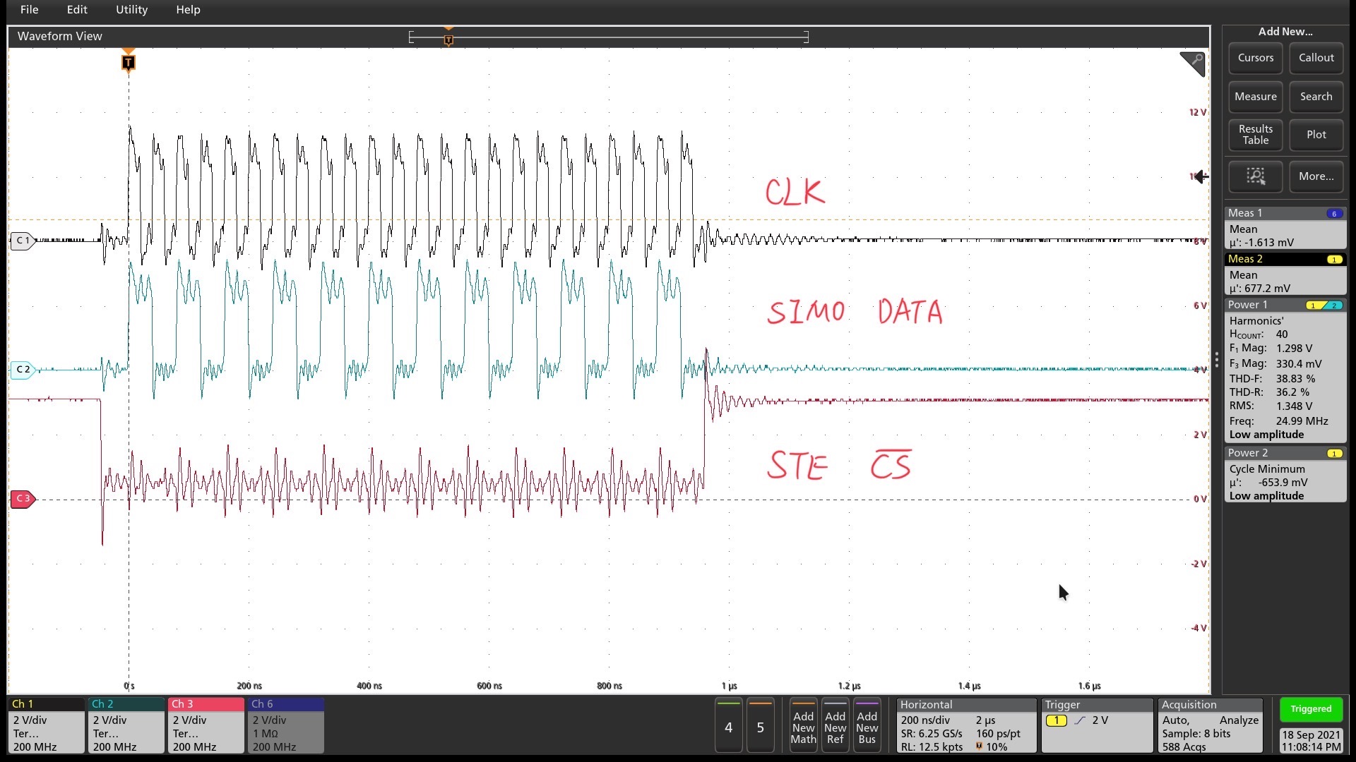
Now, if I download the code to RAM, 24 bits 0xAAAAAA can be continuously outputted, as shown in the following figure.


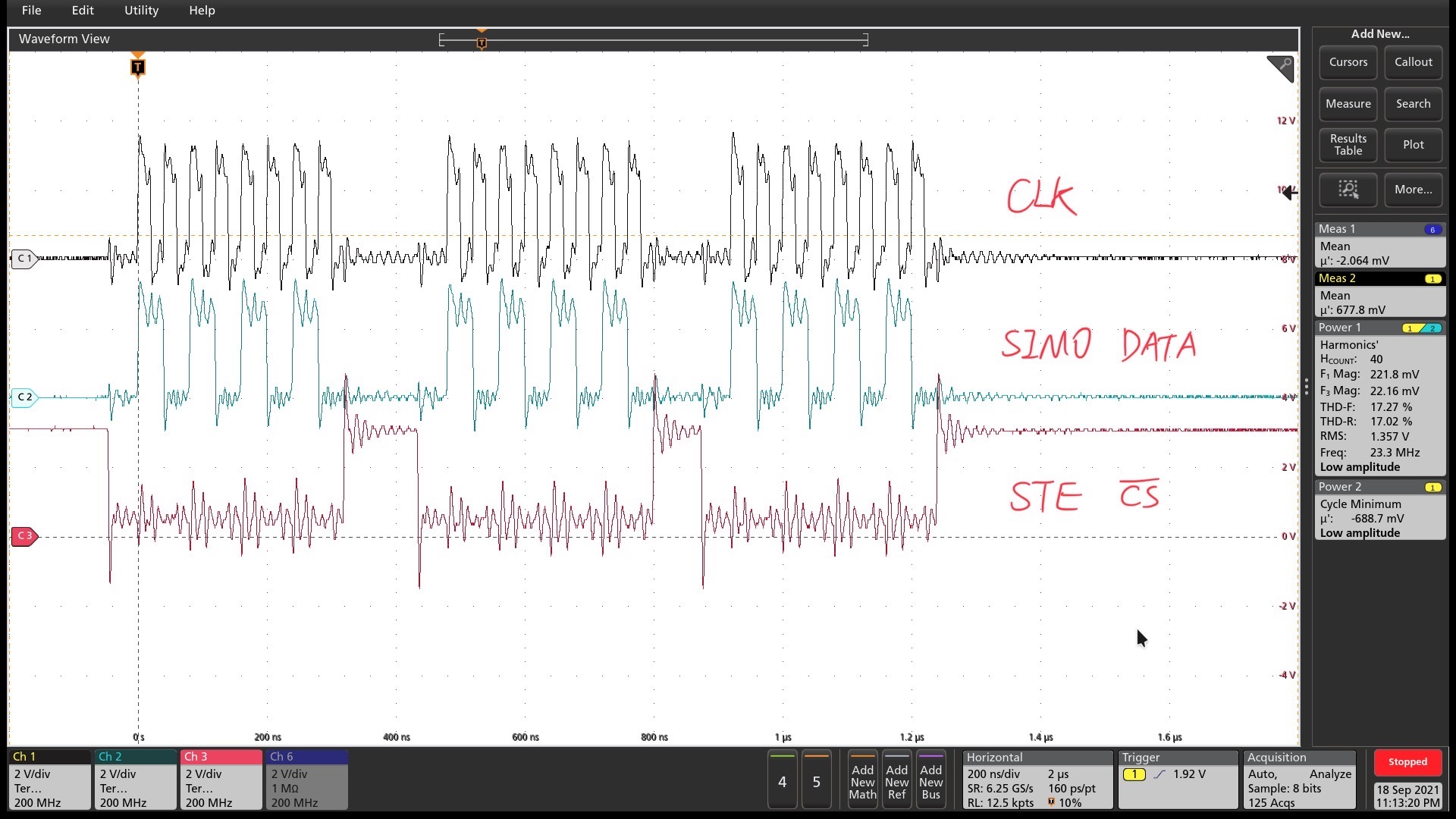
Then, if I download the code to FLASH, the output is just three sets of 8 bits, as shown in the following figure.

Thus, may I ask what should I do if I want to continuously output n sets of 8 bits SPI data to form a set of 8n bits data when downloading code to FLASH?

Thank you very much!

  • Hi Jony Wong,

    If you have configured the STE pin to be controlled by the SPI module, it is pulled high after every transfer. Looks like, in case of RAM, since the instruction fetches happen faster, the next send instruction happens before STE is pulled high.

    I would recommend you control the STE pin by software. You can configure the pin as general purpose output pin instead of SPI_STE pin and pull it high or low using the GPIO data register. You can refer to the SPI EEPROM example available in C2000ware as reference.

    Regards,

    Veena

  • Hi Veena,

    Thanks for your reply. I will use a GPIO to control the \CS pin for stability.

    Besides, May I further ask some questions about the code execution in C2000 MCU?

    If I choose CPU1_FLASH in the build configuration, _FLASH will be predefined. Then, in device.c, the following codes will be activated. Do these codes mean that the project will be copied from FLASH to RAM eventually to execute? If so, it seems that my project will finally run on RAM, then, why do the SPI results become different?

    Thank you again.

    Regards,

    Jony

  • Hi Jony,

    There are certain functions in the application marked as ramfuncs. Only those gets copied from RAM to Flash.

    For example: 

    In Flash driver, we have the following instruction which keeps the Flash_initModule under .TI.ramfunc section

    #pragma CODE_SECTION(Flash_initModule, ".TI.ramfunc");

    You can use this pragma to move additional functions to .TI.ramfunc section, as needed/

    In the cmd file, we tell the linker to load the code in Flash and run from RAM. All other functions, which is part of .text section, will reside in Flash and run from Flash.

       .TI.ramfunc      : LOAD = FLASH_BANK0_SEC1,
                          RUN = RAMLS4
                          LOAD_START(RamfuncsLoadStart),
                          LOAD_SIZE(RamfuncsLoadSize),
                          LOAD_END(RamfuncsLoadEnd),
                          RUN_START(RamfuncsRunStart),
                          RUN_SIZE(RamfuncsRunSize),
                          RUN_END(RamfuncsRunEnd),
                          PAGE = 0, ALIGN(4)
    Regards,
    Veena
  • Hi Veena,

    Thank you for your help. I understand now.

    Regards,

    Jony