Hi all,
We are starting manufacturing of a control board that uses F28069U as the central DSP, we had completed our tests on our prototypes and before starting the main production, we manufactured 12 units just to see how is their behaviour and we got a big surprise which is almost all the 12 boards showing inconsistency in Power-up process and the details of the issue is as below:
Our system can turn ON at any time with any frequency ( like Turn ON/OFF every 2 seconds or more ) , now we have our code running on these boards, and we are randomly trying to turn them ON and OFF, most of the time the code starts right after Power up, and there is a LED on the board that will blink if the code is not frozen( we, of course, checked all the other functionalities), however, let's say 2 out of 10 times, the DSPs don't boot up and they stay frozen, the LED is also staying off, until we have to recycle the power again.
After power recycling, mostly they start to work again but sometimes it requires multiple power recycling until the DSP can boot up again...
To this date, This behaviour has never been seen in the prototype which has the exact same circuit and components ( the 12 boards are its clones)!
Given this big headache, we started to investigate what is causing the issue, I started by checking the Voltages, transients at startup and so on, but everything seems good, there is no current drop or abnormal behaviour in the supply transients once we get the DSP frozen condition. ( the XRS stays always high and I think this seem to show there are no Brownout or other power-related issues, ...)
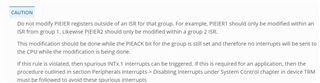
After this, I move to check the code, and I figure out a very strange thing, which was the DSPs in production fail in the following function:
void enable_interrupts()
{
EALLOW;
PieVectTable.ADCINT1 = &ADCINT1_isr; /* Hook interrupt to the ISR*/
EDIS;
PieCtrlRegs.PIEIER1.bit.INTx1 = 1; /* Enable interrupt ADCINT1*/
IER |= M_INT1;
EALLOW;
PieVectTable.EQEP1_INT = &EQEP1_INT_isr;/* Hook interrupt to the ISR*/
EDIS;
PieCtrlRegs.PIEIER5.bit.INTx1 = 1; /* Enable interrupt EQEP1_INT*/
IER |= M_INT5;
EALLOW;
PieVectTable.SCIRXINTA = &SCIRXINTA_isr;/* Hook interrupt to the ISR*/
EDIS;
PieCtrlRegs.PIEIER9.bit.INTx1 = 1; /* Enable interrupt SCIRXINTA*/
IER |= M_INT9;
EALLOW;
PieVectTable.ECAP1_INT = &ECAP1_INT_isr;/* Hook interrupt to the ISR*/
EDIS;
PieCtrlRegs.PIEIER4.bit.INTx1 = 1; /* Enable interrupt ECAP1_INT*/
IER |= M_INT4;
EALLOW;
PieVectTable.ECAP2_INT = &ECAP2_INT_isr;/* Hook interrupt to the ISR*/
EDIS;
PieCtrlRegs.PIEIER4.bit.INTx2 = 1; /* Enable interrupt ECAP2_INT*/
IER |= M_INT4;
EALLOW;
PieVectTable.ECAP3_INT = &ECAP3_INT_isr;/* Hook interrupt to the ISR*/
EDIS;
PieCtrlRegs.PIEIER4.bit.INTx3 = 1; /* Enable interrupt ECAP3_INT*/
IER |= M_INT4;
EALLOW;
PieVectTable.ECAN0INTA = &ECAN0INTA_isr;/* Hook interrupt to the ISR*/
EDIS;
PieCtrlRegs.PIEIER9.bit.INTx5 = 1; /* Enable interrupt ECAN0INTA*/
IER |= M_INT9;
// EALLOW;
// PieVectTable.ADCINT1 = &ADCINT1_isr; /* Hook interrupt to the ISR*/
// PieVectTable.EQEP1_INT = &EQEP1_INT_isr;/* Hook interrupt to the ISR*/
// PieVectTable.SCIRXINTA = &SCIRXINTA_isr;/* Hook interrupt to the ISR*/
// PieVectTable.ECAP1_INT = &ECAP1_INT_isr;/* Hook interrupt to the ISR*/
// PieVectTable.ECAP2_INT = &ECAP2_INT_isr;/* Hook interrupt to the ISR*/
// PieVectTable.ECAP3_INT = &ECAP3_INT_isr;/* Hook interrupt to the ISR*/
// PieVectTable.ECAN0INTA = &ECAN0INTA_isr;/* Hook interrupt to the ISR*/
// EDIS;
//
// PieCtrlRegs.PIEIER1.bit.INTx1 = 1; /* Enable interrupt ADCINT1*/
// IER |= M_INT1;
// PieCtrlRegs.PIEIER5.bit.INTx1 = 1; /* Enable interrupt EQEP1_INT*/
// IER |= M_INT5;
// PieCtrlRegs.PIEIER9.bit.INTx1 = 1; /* Enable interrupt SCIRXINTA*/
// IER |= M_INT9;
// PieCtrlRegs.PIEIER4.bit.INTx1 = 1; /* Enable interrupt ECAP1_INT*/
// IER |= M_INT4;
// PieCtrlRegs.PIEIER4.bit.INTx2 = 1; /* Enable interrupt ECAP2_INT*/
// IER |= M_INT4;
// PieCtrlRegs.PIEIER4.bit.INTx3 = 1; /* Enable interrupt ECAP3_INT*/
// IER |= M_INT4;
// PieCtrlRegs.PIEIER9.bit.INTx5 = 1; /* Enable interrupt ECAN0INTA*/
// IER |= M_INT9;
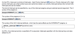
/* Enable global Interrupts and higher priority real-time debug events:*/
EINT; /* Enable Global interrupt INTM*/
ERTM; /* Enable Global realtime interrupt DBGM*/
}
and the exact point of failure is when the code hooks the ECAP1 to the ISR as :
EALLOW;
PieVectTable.ECAP1_INT = &ECAP1_INT_isr;/* Hook interrupt to the ISR*/
EDIS;
Right after this piece of code in faulty DSPs the system goes into a halt or frozen mode (occasionally and Not Always), I found this by putting another GPIO enabling and I tracked down the problem to here since my code now is running from Flash through a boot loader ( USB bootload written for DFUprog), now I'm going to explain some other important observations:
- our control cards don't have a JTAG locally mounted, so whenever the DSPs are frozen, right after I connect the JTAG they go back to normal operation!! the LED starts to blink and it seems everything is going great, also as long as the JTAG is in-circuit the code never fails...
- I tried to use our Watch-dog and the point is the Watch-dog whenever the failure occurs keeps resetting the board, but it can never recover it back to normal operation until I fully recycle the power ( we are using software watchdog not NMI)
- on our board, we don't have the GPIO 34 or TDO pulled up externally. ( I checked, even with external pull-ups there is no difference and it seems the issue is not the boot mode selection...)
- To eliminate the effect of the Boot-loader, I removed it, and I made our code stand-alone, just to be sure the boot-loader is not causing the issue, and again without the boot-loader, the code halts in the same spot occasionally and not always ( I wish it was always)
- I have attached here for you our Linker command file for our system.
here are the Serial Numbers engraved on the Faulty and Working F28069U :
Faulty: F28069UPNT - G4A - 08AFXHW - G4
Working: F28069UPNT - G4A - 99C4EXW - G4
I couldn't find a way to track down the production date of these chips but it appears to me by some speculations that the faulty ones are older as in the 3rd section it starts with Zero...
So now the question is This:
Is this a hardware problem or software problem and how to solve it?
Thanks in advance
John