This thread has been locked.

If you have a related question, please click the "Ask a related question" button in the top right corner. The newly created question will be automatically linked to this question.

TMS320F28379D: ePWM and trip zone DAC problem

Part Number: TMS320F28379D
Other Parts Discussed in Thread: C2000WARE

Hello, I have a project with 8 dc brush motors. Each has a bidirectional current sense in series with the coil. I need to have a cycle by cycle current limit for plus and minus current, based on the ADC input.

I've figured out a bunch of peripherals on C2000, but the trip zone stuff is the most confusing.

Each of 8 motors has two PWM's, one ADC and one compare.

One motor is setup so far, like this

XBAR_setEPWMMuxConfig(XBAR_TRIP5, XBAR_EPWM_MUX08_CMPSS5_CTRIPH_OR_L);

XBAR_enableEPWMMux(XBAR_TRIP5, XBAR_MUX08);

for(cnt = 0; cnt < 2; cnt++){  // each motor has two pwm's

  EPWM_selectDigitalCompareTripInput(obj->pwmHandle[cnt],EPWM_DC_TRIP_TRIPIN5, EPWM_DC_TYPE_DCAH);

  EPWM_setTripZoneDigitalCompareEventCondition(obj->pwmHandle[cnt], EPWM_TZ_DC_OUTPUT_A1, EPWM_TZ_EVENT_DCXH_HIGH);

  EPWM_setDigitalCompareEventSource(obj->pwmHandle[cnt], EPWM_DC_MODULE_A, EPWM_DC_EVENT_1, EPWM_DC_EVENT_SOURCE_ORIG_SIGNAL);

  EPWM_setDigitalCompareEventSyncMode(obj->pwmHandle[cnt], EPWM_DC_MODULE_A, EPWM_DC_EVENT_1, EPWM_DC_EVENT_INPUT_NOT_SYNCED);

  EPWM_setTripZoneAction(obj->pwmHandle[cnt], EPWM_TZ_ACTION_EVENT_DCAEVT1, EPWM_TZ_ACTION_LOW);

  EPWM_clearTripZoneFlag(obj->pwmHandle[cnt], (EPWM_TZ_FLAG_OST | EPWM_TZ_FLAG_DCAEVT1 | EPWM_TZ_FLAG_CBC ));

}

In my main loop, I can set the limit like this:

CMPSS_setDACValueHigh(obj->cmpssHandle, high);   // cmpssHandle is set to CMPSS5_BASE to match with XBAR_TRIP5 above

CMPSS_setDACValueLow(obj->cmpssHandle, low); 

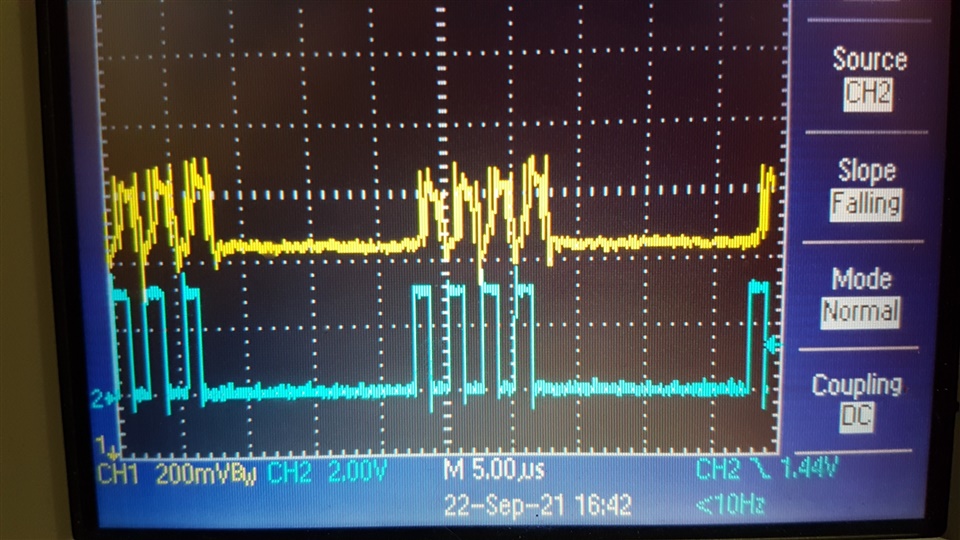
When moving negative direction, so first PWM is 'on' and ADC drops from ref, I can see my raw ADC count at about 3500  (mid point is 3600), When I bring my 'low' limit up from zero, it starts to limit my pwm when it gets to around 3100. 

Similarly, if I move positive, so second PWM is 'on', I see my raw ADC at about 3700, but my pwm only starts to chop when my 'high'  limit gets below about 3300

I can't figure out why my DACValue doesn't match my ADC. I have confirmed my ADC count matches what I measure on the ADC input.

Am I setting the TripZone stuff up correctly?

I've found a couple of examples, but both are too different from what I'm trying to do.

thanks

Ken

  • Ken,

    I'm not quite able to understand the problem statement in terms of a specific fault at the module level. Would you be able to elaborate?

    For debug, I generally recommend outputting the CMPSS CTRIPOUT signals to GPIO pins via XBAR OUTPUT. This will allow you to directly observe what the comparators outputs are doing. More often than not, there is some noise component that is not obvious.

    -Tommy

  • Thanks for the reply.

    The problem is the CMPSS trip point does not match up to the ADC value. I can see CMPSS_getStatus is set when I see the PWM start to cut out. But this is not at the correct ADC reading.

    Since this seems impossible, I suspect instead that I've configured it wrong and it's just a coincidence that it works at all. But I can't find an example to help me find what's wrong.

    Have I made the settings required for dual PWM and single ADC and comparator CBC ?

    thanks

  • The problem is the CMPSS trip point does not match up to the ADC value.

    The CMPSS and ADC are independent modules with uncorrelated errors. I would not be surprised to see differences between CMPSS trip reference LSBs vs ADC converted LSBs.

    If you are using the LaunchPad, the CMPSS full-scale reference is 3.3V by default, whereas the ADC full-scale reference is 3.0V.

    I can see CMPSS_getStatus is set when I see the PWM start to cut out.

    If the CMPSS output is feeding the PWM trip, there should be a direct correlation between the comparator trip vs PWM cut out.

    But this is not at the correct ADC reading.

    In addition to uncorrelated errors between CMPSS and ADC, the act of sampling the input signal with the ADC will introduce some amount of feedback disturbance that may interfere with the CMPSS, and the ADC may include additional errors if the input characteristics are not matched with the ACQPS sampling window.

    Have I made the settings required for dual PWM and single ADC and comparator CBC ?

    If the gross behavior is matching expectations, I would assume that the configuration is correct but further debug is required to investigate the accuracy. Observing the CTRIPOUT signal can be very informative.

    If the gross behavior is not matching, then I would evaluate the configuration.

    Example of gross behavior: The CMPSS is expected to trip the PWM output when the input signal exceeds an approximate threshold voltage.

  • I am using the launchpad. I didn't realize the CMP and ADC are on different references. That helps, but still quite a bit off. An additional 10% fudge factor on the gain makes it trip at about the right point.

    I can live with this, but it seems odd. I know there will be other errors, but this seems excessive. Is this common?

    The other thing that doesn't work as expected is when the PWM trips, it goes 'off', but turns back 'on' before the next cycle. So my 40KHz, 40% duty cycle 'on' time is 10usec. When it trips, I get 4 pulses, each 1usec long, within each 'on' time. 

    It actually is ok for me, since I have very low time constant motors, but I was expecting it to stay 'off' until the counter resets. Can you help explain that?

    If the pic works, blue is my FWD PWM and yellow is amplified current shunt during a CBC trip  

    thanks

    Ken

  • I didn't realize the CMP and ADC are on different references.

    I would recommend reviewing the Analog Subsystem diagram in the TRM or datasheet for a high level idea of how references are derived:

    The LaunchPad schematics can be found in both the User's Guide and C2000Ware.

    I know there will be other errors, but this seems excessive. Is this common?

    The device itself will meet the datasheet specifications. There are board and system variables (like software configuration and signal conditioning) that may degrade performance if they are not properly managed.

    The other thing that doesn't work as expected is when the PWM trips, it goes 'off', but turns back 'on' before the next cycle.

    Note that CBC trip events are only derived from DCxEVT2:

    Also be sure to explicitly configure unused TZCTL events to Do Nothing because the default action is High-Impedance, which may override your desired actions.

    Can you help explain that?

    It is likely that the EPWM output is responding to a raw DCxEVT signal, rather than the CBC signal.

  • ok, I'm getting much closer, but still something not right. Appreciate your help.

    I can see I'm getting  EPWM_getTripZoneFlagStatus  = x12 (EPWM_TZ_FLAG_DCAEVT2 | EPWM_TZ_FLAG_CBC). Seems correct

    But the PWM doesn't shut off. I have it configured as:

    EPWM_selectDigitalCompareTripInput(obj->pwmHandle[cnt], EPWM_DC_TRIP_TRIPIN5, EPWM_DC_TYPE_DCAH);

    EPWM_setTripZoneDigitalCompareEventCondition(obj->pwmHandle[cnt], EPWM_TZ_DC_OUTPUT_A2, EPWM_TZ_EVENT_DCXH_HIGH);

    EPWM_setDigitalCompareEventSource(obj->pwmHandle[cnt], EPWM_DC_MODULE_A, EPWM_DC_EVENT_2, EPWM_DC_EVENT_SOURCE_ORIG_SIGNAL);

    EPWM_setDigitalCompareEventSyncMode(obj->pwmHandle[cnt], EPWM_DC_MODULE_A, EPWM_DC_EVENT_2, EPWM_DC_EVENT_INPUT_NOT_SYNCED);

    EPWM_enableTripZoneSignals(obj->pwmHandle[cnt], EPWM_TZ_SIGNAL_DCAEVT2); 

    EPWM_setTripZoneAction(obj->pwmHandle[cnt], EPWM_TZ_ACTION_EVENT_DCAEVT2, EPWM_TZ_ACTION_LOW);

    If I add this, it seems to work correctly, 

    EPWM_setTripZoneAction(obj->pwmHandle[cnt], EPWM_TZ_ACTION_EVENT_TZA, EPWM_TZ_ACTION_LOW);

    But I can't understand why this is needed. If the DCAEVT2 triggers, and I set the action to 'low', what am I missing?

  • Ken,

    I suspect that the CBC signal is not enabled

    It might be helpful to reference the CBC settings from a working C2000Ware example:

    ~\C2000Ware_XXXX\driverlib\f2837xd\examples\cpu1\epwm\epwm_ex1_trip_zone.c

    If that doesn't help, I'll pull in the EPWM expert.

    -Tommy

  • yes, I've been looking at that example. The problem is, it uses a GPIO to trigger the trip, so it uses TZ1. I'm using the COMPSS, so I should be using DCAEVT2 (I think)

    It would be great if the EPWM expert could have a look. I've tried everything I can think of

  • Hi Ken,

    EPWM_setTripZoneAction(obj->pwmHandle[cnt], EPWM_TZ_ACTION_EVENT_DCAEVT2, EPWM_TZ_ACTION_LOW);

    If I add this, it seems to work correctly, 

    EPWM_setTripZoneAction(obj->pwmHandle[cnt], EPWM_TZ_ACTION_EVENT_TZA, EPWM_TZ_ACTION_LOW);

    But I can't understand why this is needed. If the DCAEVT2 triggers, and I set the action to 'low', what am I missing?

    If you use the first line of code referenced above, the output will only take the effect defined by the trip zone control registers for the duration of the trip pulse and then will automatically go back to how it was. 

    If you want to set an action for when the CBC trip signal occurs you have to set the action through the TZA register.

    Therefore, for what you are trying to do, you should only need the following line:

    EPWM_setTripZoneAction(obj->pwmHandle[cnt], EPWM_TZ_ACTION_EVENT_TZA, EPWM_TZ_ACTION_LOW);

    Best Regards,

    Marlyn

  • ok, thanks. That does seem to work, just not wrapping my head around why. I find this section of the datasheet not easy to understand.

    Does it make more sense in this type of application (CBC based on one ADC), to use the ADC PPB limits as shown in   example adc_ex10_ppb_pwm_trip.c

    Could I do 8 independent limits that way?

    For what reason would it be better to use PPB limits, rather than COMPSS limits?

    best regards

    Ken

  • ok, thanks. That does seem to work, just not wrapping my head around why. I find this section of the datasheet not easy to understand.

    It's confusing for most of us as well. The module has adopted multiple incremental features over the years while striving to preserve backward compatibility at the same time. This can lead to some strange caveats.

    Does it make more sense in this type of application (CBC based on one ADC), to use the ADC PPB limits as shown in   example adc_ex10_ppb_pwm_trip.c

    This really depends on your system requirements. For most applications where CBC trips are used, there is a need for continuous monitoring and/or fast trip response times.

    The CMPSS has an analog comparator that will continuously sense the input signal and offers a response time that is well under 100ns. Whereas the ADC can only sense periodic conversions, which may miss spurious spikes and would have an effective response time that is limited to its sampling rate + PPB processing time (roughly 300ns+).

    Further, there is an ADC-PPB->EPWM-DC related advisory in the errata, which indicates that the PPB trip signaling to EPWM is not 100% reliable: ADC PPB Event Trigger (ADCxEVT) to ePWM Digital Compare Submodule

    Could I do 8 independent limits that way?

    With 4 PPB x 2 Limits, technically yes with the qualification that the 2 PPB Limits are implemented as Windowed limits with no option to invert the trip condition.

    For what reason would it be better to use PPB limits, rather than COMPSS limits?

    PPB would probably be best suited for coarse, high-latency trip detection. For example, if you are monitoring a slow moving environmental sensor and want to know when some condition is met.