This thread has been locked.

If you have a related question, please click the "Ask a related question" button in the top right corner. The newly created question will be automatically linked to this question.

TMS320F280025C: phase shift PCMC , some question obout SR PWM

Part Number: TMS320F280025C
Other Parts Discussed in Thread: TIDM-02000

HI all:


1.I want to use 280025C  to PCMC;

2.the code is reference  tidm_02000;

3.open loop test i find some problem:

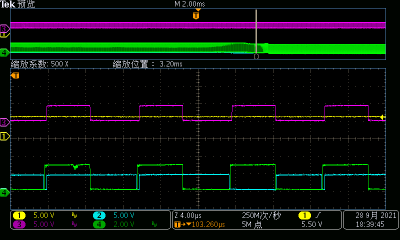
when HV current(for peak current) is bigger than rampmaxvalue,epwm4A/4B(SR PWM) is  abnormal.

the waves is follow:

CHANNAL 2(bule): EPWM4B

CHANNAL 4(green): EPWM4A

CHANNAL 1(yellow): peak current

CHANNAL 3(): EPWM2B

the whole progress:

i do not find the reson  and how to solve it?

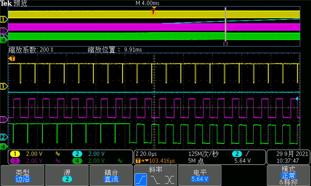
  • add

         similar configuration for 280049C. the result is blow.


          there is not understand the difference is EPWM4A/4B,but it can works.


  • Hi Chenghu,

    Can you please clarify on your setup? My understanding is that you tested the PCMC solution from TIDM-02000 on F280049C and works fine. Then you did a porting from F280049C to F280025C and had the issue described in your first post. Can you please confirm?

    The channel 1 looks like a constant line and does not have the current peaks due to switching. Can you please confirm this is the current feedback for PCMC? Have you tested the control in open loop and see if the waveforms looks fine?

    Also the greed signal does not look like a digital signal, and has many intermediate noises in there. This type of issue does not look like caused by a wrong software / MCU output. Can you please confirm which signal is that and where and how did you probed it? Thanks.

    Han

  • HI Han:

         1.yes.PWM and cmpss and DC configuration are the same, just PWM synamic signal is difference.

         2.the test condition is open loop,.i want to just test PWM operation when the different fedback current.so the cmpss input is constan value ,and slope is also constant.the fedback(PCMC) is also constant value with slow change.

         3. using same board,use VMC control ,green signal is ok,no intermediate noises.

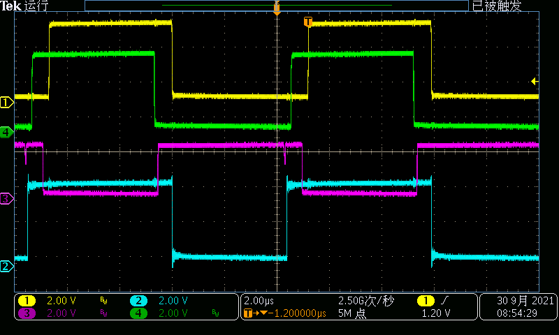
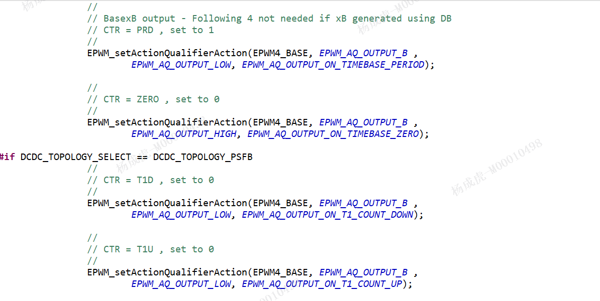
             and i find , when the fedbck(PCMC) is low than DCVMAXREF,is also has this noises,and happen on T1U and T1D , and seems directly operater TZ signal,not AQ.


    change the PCMC fedback signal


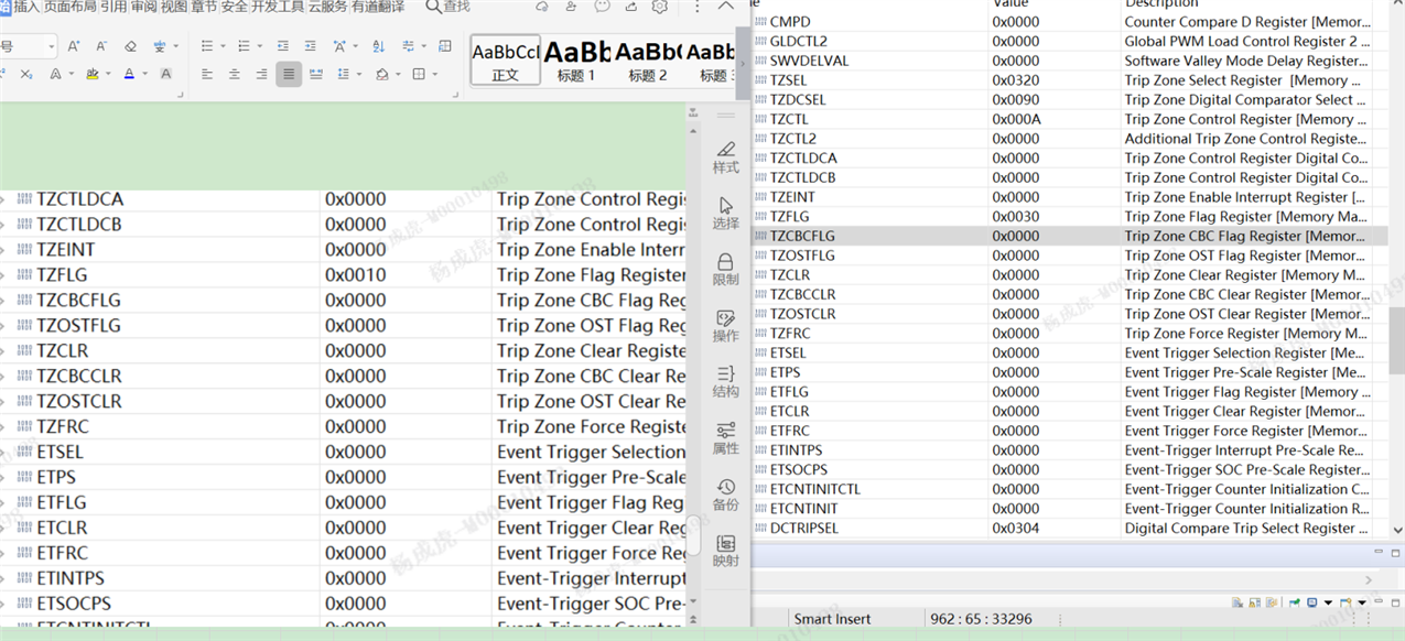
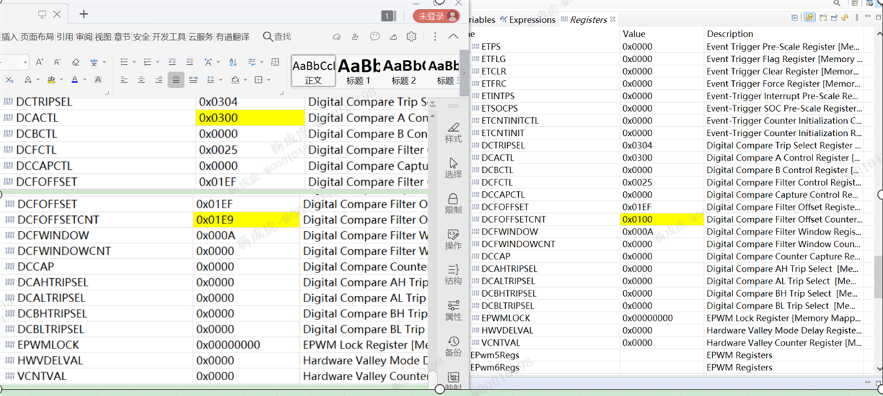
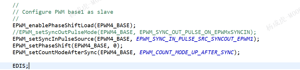
  • I want to check all PWM configuration register between 280049 and 280025 in next step.

  • Yes, please try to do the register comparison.

    There is one difference between the F280049C and F280025C ePWM module: we have added additional flexibility on the Sync mechanism and you can select any PWM SYNC output as the sync in signal and set on EPWMSYNCINSEL resister. But since it by default always sync to ePWM1, it should not bring you big issue in most cased.

  • HI han

        I check the PWM4 configuration,the result is the same. the difference is TZSEL.28004X enable oneshort1 and oneshor2.actually current condition those signal  is not work.


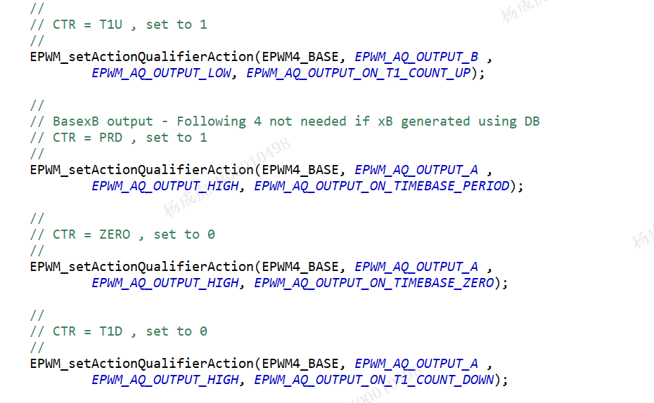
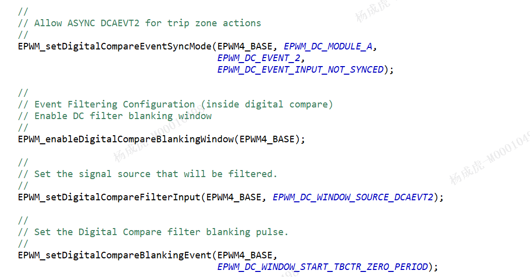
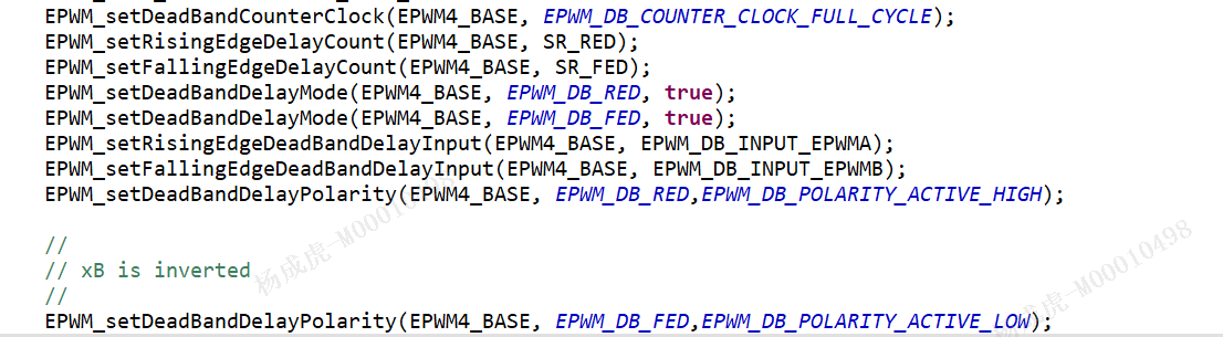
  • add by EPWM4 configuration

    test condition is SRMode = 2;