This thread has been locked.

If you have a related question, please click the "Ask a related question" button in the top right corner. The newly created question will be automatically linked to this question.

TMDXIDDK379D: Problem of current sampling method in FCL routine

Part Number: TMDXIDDK379D
Other Parts Discussed in Thread: C2000WARE

Dear team:

C:\ti\c2000\C2000Ware_MotorControl_SDK_3_03_00_00\solutions\tmdxiddk379d\docs

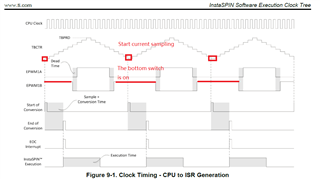
In the document, the current sampling method used in the FCL routine for 28388D is to sample two of the three-phase currents. Namely: 2 Hall current sensors are connected in series with 2 phases, or 2 sampling resistors are connected in series with 2 phases.

My customer wants to know: If the method of connecting 3 sampling resistors in series between the 3 bridge arm downtubes and the DC negative terminal respectively, can the FCL library in the example be applied?

If not applicable, how to modify the FCL library if the customer wants to use the above method to sample?

Best regards

  • The only change needed would be in the Clarke transform beta axis calculation.

    It will have to change to (Ib-Ic)/sqrt(3). No other changes.

  • Thanks.

    Is there any document available about that change?

    Witch  sampling mode should be adopted:  Single sampling or double sampling? Some other settings are kept unchanged for FCL?

  • This is a trivial change, so no exclusive documentation is given.

    with double sampling, maximum current loop bandwidth will be twice that of single sampling. So, it is user's choice.

  • About current sampling, the below figure from 28069 document could be a reference for the three resistors connected  between the 3 bridge arm downtubes and the DC negative terminal solution.

    In the document, the current sampling time constant happens when PWM timer counter number =0 for the up-down PWM mode. It is easy to understand since when the counter=0, the bottom switch on the bridge arm is on state and the current flows through the resistor, at that moment, current sampling is reasonable.

    But for 28388D, in the example program, for single sampling, the SOC setting is at the counter= PWM period. With reference to the above solution, it seems to be not feasible to execute current sampling at that moment for the hardware solution here.

    For double sampling mode, the SOC setting is at Counter =0 or counter= pieriod. For counter=0, it looks ok.

    Therefore, my concern is whether the above two current sampling modes do not practical for the mentioned hardware solution in this post. Is it needed to be changed as at counter =0, for example, for single sampling mode ?

    If that changing is necessary for the this post hardware, then any other settings in the example program should also be changed accordingly?

  • sampling at CNTR=0 or PRD depends on the topology of current sensing. If sensing is at the bottom of inverter switches, then you are right. In our example, we use in phase current sensing where current always flows through the sensing element.

    The user guide gives details of what changes can be tried.

  • Thank you. Yes, in this post, the current sensing is at the bottom of inverter switches. In addition, there are three current sensing resistors mentioned in this post, so my question is how to modify the example accordingly ?  (I think not only  modifying the sampling at counter=0 but not at counter = period for example  in single sampling mode, but also need to modify other settings accordingly, I believe). By the way, I use my customized PCB board on which three sampling resistors are connected at the bottom inverter arms respectively. So this is the cause why I need to make sure the issue more clear so as to modify and implement the example on my hardware.

    In addition, Since I only have find one document named " Design Drive IDDK user's guide.pdf" to help to understand the example, but I think it is too simple to help me to understand the example well. Is there any other document available that can help me to well understand the example?

  • Thanks for your answer. But when sampling at CNTR=0 only, the latency is much bigger, can the FCL  still function normally and keep high bandwidth?

  • You can verify your experimental sensing schemes in LEVEL2 which is mainly for this purposes only. The motor runs in open loop and see if your custom sensing works fine.

    Related user guides are available at 

    C:\ti\c2000\C2000Ware_MotorControl_SDK_3_01_00_00\solutions\tmdxiddk379d\docs

    You have to ensure that the sampling time and ISR time are same. Otherwise, it may mess up the latency.

  • Thanks for your answer. I will have a try in Level2.