This thread has been locked.

If you have a related question, please click the "Ask a related question" button in the top right corner. The newly created question will be automatically linked to this question.

TMS320F28069: SCI received overflow but did not enter interrupt

Part Number: TMS320F28069
Other Parts Discussed in Thread: C2000WARE

Hi Expert,

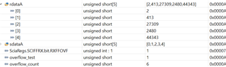
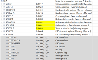
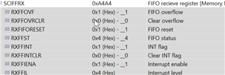
My customer are facing an issue that SCI receive overflow and SciaRegs.SCIFFRX.bit.RXFFOVF is 1, but sometimes did not go to the interrupt.

as the TRM mention, when SCI receive overflow occur, there should be able to go to the interrupt. 

I did the test with control card and modified the code from c2000ware as below, when set overflow_test=1 in ccs windows, there will not read data and will cause receive data overflow:

in sciaRxFifoIsr also reset the SCI according to flag SciaRegs.SCIFFRX.bit.RXFFOVF.

sciaRxFifoIsr(void)
{
    Uint16 i;

    if(SciaRegs.SCIFFRX.bit.RXFFOVF ==1)
    {
         overflow_test = 0;
         SciaRegs.SCICTL1.all = 0x0023;
         SciaRegs.SCIFFTX.bit.TXFIFOXRESET = 1;
         SciaRegs.SCIFFRX.bit.RXFIFORESET = 1;
         overflow_count++;


    }
    if(overflow_test ==0)
    {
        for(i=0;i<1;i++)
            rdataA[i]=SciaRegs.SCIRXBUF.all;  // Read data
    }

Just set overflow_test to 1 and see the result, did the test several times will find that, SciaRegs.SCIFFRX.bit.RXFFOVF is 1, but did not enter the interrupt sciaRxFifoIsr  again.  

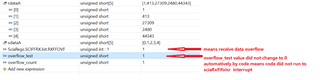
Anything wrong here? why would have case that SciaRegs.SCIFFRX.bit.RXFFOVF is 1 but the code did not run to sciaRxFifoIsr  ?

  • Hello Strong,

    What is the value of RXFFIL? Can you also check the value of RXFFST to see if there data in the RX Buffer?

    In the screenshot you attached, overflow_count is equal to 1 (seen in the expressions window), is it initially 0? This would mean that the ISR was entered and its value was increased.

    Best Regards,

    Marlyn

  • Hi Marlyn,

    Sorry I forgot to attach the code.

    at the beginning, overflow_test is 0, when set it to 1 in CCS window, there will trigger overflow, 

    If the code run to ISR when overflow occur, then overflow_count  value will increase, which means it work as expected.

    otherwise there will no changed, which means the code did not run to ISR while  SciaRegs.SCIFFRX.bit.RXFFOVF is 1, and this is the issue.

    Below are the register that did not work as expect:

    I also post the code so that you can reproduce the issue with control card. 

    https://e2e.ti.com/cfs-file/__key/communityserver-discussions-components-files/171/scia_5F00_loopback_5F00_interrupts.7z

  • Hi Strong,

    Can you please provide the .c file that you modified?

    Also, when the overflow occurs can you please check the value of RXFFST? 

    Best Regards,

    Marlyn

  • Marlyn,

    I already post the project include c file, and RXFFST is showed below:

    //###########################################################################
    //
    // FILE:   Example_2806xSci_FFDLB_int.c
    //
    // TITLE:  SCI Digital Loop Back with Interrupts Example
    //
    //!  \addtogroup f2806x_example_list
    //!  <h1>SCI Digital Loop Back with Interrupts(scia_loopback_interrupts)</h1>
    //!
    //!  This program uses the internal loop back test mode of the peripheral.
    //!  Other then boot mode pin configuration, no other hardware configuration
    //!  is required. Both interrupts and the SCI FIFOs are used.
    //!
    //!  A stream of data is sent and then compared to the received stream.
    //!  The SCI-A sent data looks like this: \n
    //!  00 01 \n
    //!  01 02 \n
    //!  02 03 \n
    //!  .... \n
    //!  FE FF \n
    //!  FF 00 \n
    //!  etc.. \n
    //!  The pattern is repeated forever.
    //!
    //!  \b Watch \b Variables \n
    //!  - \b sdataA , Data being sent
    //!  - \b rdataA , Data received
    //!  - \b rdata_pointA ,Keep track of where we are in the datastream.
    //!    This is used to check the incoming data
    //
    //###########################################################################
    // $TI Release: F2806x Support Library v2.06.00.00 $
    // $Release Date: Fri Feb 12 19:15:11 IST 2021 $
    // $Copyright:
    // Copyright (C) 2009-2021 Texas Instruments Incorporated - http://www.ti.com/
    //
    // Redistribution and use in source and binary forms, with or without 
    // modification, are permitted provided that the following conditions 
    // are met:
    // 
    //   Redistributions of source code must retain the above copyright 
    //   notice, this list of conditions and the following disclaimer.
    // 
    //   Redistributions in binary form must reproduce the above copyright
    //   notice, this list of conditions and the following disclaimer in the 
    //   documentation and/or other materials provided with the   
    //   distribution.
    // 
    //   Neither the name of Texas Instruments Incorporated nor the names of
    //   its contributors may be used to endorse or promote products derived
    //   from this software without specific prior written permission.
    // 
    // THIS SOFTWARE IS PROVIDED BY THE COPYRIGHT HOLDERS AND CONTRIBUTORS 
    // "AS IS" AND ANY EXPRESS OR IMPLIED WARRANTIES, INCLUDING, BUT NOT 
    // LIMITED TO, THE IMPLIED WARRANTIES OF MERCHANTABILITY AND FITNESS FOR
    // A PARTICULAR PURPOSE ARE DISCLAIMED. IN NO EVENT SHALL THE COPYRIGHT 
    // OWNER OR CONTRIBUTORS BE LIABLE FOR ANY DIRECT, INDIRECT, INCIDENTAL, 
    // SPECIAL, EXEMPLARY, OR CONSEQUENTIAL DAMAGES (INCLUDING, BUT NOT 
    // LIMITED TO, PROCUREMENT OF SUBSTITUTE GOODS OR SERVICES; LOSS OF USE,
    // DATA, OR PROFITS; OR BUSINESS INTERRUPTION) HOWEVER CAUSED AND ON ANY
    // THEORY OF LIABILITY, WHETHER IN CONTRACT, STRICT LIABILITY, OR TORT 
    // (INCLUDING NEGLIGENCE OR OTHERWISE) ARISING IN ANY WAY OUT OF THE USE 
    // OF THIS SOFTWARE, EVEN IF ADVISED OF THE POSSIBILITY OF SUCH DAMAGE.
    // $
    //###########################################################################
    
    //
    // Included Files
    //
    #include "DSP28x_Project.h"     // Device Headerfile and Examples Include File
    
    //
    // Defines
    //
    #define CPU_FREQ    90E6
    #define LSPCLK_FREQ (CPU_FREQ/4)
    #define SCI_FREQ    100E3
    #define SCI_PRD     ((LSPCLK_FREQ/(SCI_FREQ*8))-1)
    
    //
    // Function Prototypes
    //
    __interrupt void sciaTxFifoIsr(void);
    __interrupt void sciaRxFifoIsr(void);
    __interrupt void scibTxFifoIsr(void);
    __interrupt void scibRxFifoIsr(void);
    void scia_fifo_init(void);
    void scib_fifo_init(void);
    void error(void);
    
    //
    // Globals
    //
    Uint16 sdataA[5];    // Send data for SCI-A
    Uint16 rdataA[5];    // Received data for SCI-A
    Uint16 rdata_pointA; // Used for checking the received data
    Uint16 overflow_test=0;
    Uint16 overflow_count=0;
    
    //
    // Main
    //
    void main(void)
    {
        Uint16 i;
    
        //
        // Step 1. Initialize System Control:
        // PLL, WatchDog, enable Peripheral Clocks
        // This example function is found in the F2806x_SysCtrl.c file.
        //
        InitSysCtrl();
    
        //
        // Step 2. Initalize GPIO:
        // This example function is found in the F2806x_Gpio.c file and
        // illustrates how to set the GPIO to it's default state.
        //
        //InitGpio();
        
        //
        // Setup only the GP I/O only for SCI-A and SCI-B functionality
        // This function is found in F2806x_Sci.c
        //
        InitSciGpio();
    
        //
        // Step 3. Clear all interrupts and initialize PIE vector table:
        // Disable CPU interrupts
        //
        DINT;
    
        //
        // Initialize PIE control registers to their default state.
        // The default state is all PIE interrupts disabled and flags
        // are cleared.
        // This function is found in the F2806x_PieCtrl.c file.
        //
        InitPieCtrl();
    
        //
        // Disable CPU interrupts and clear all CPU interrupt flags
        //
        IER = 0x0000;
        IFR = 0x0000;
    
        //
        // Initialize the PIE vector table with pointers to the shell Interrupt
        // Service Routines (ISR).
        // This will populate the entire table, even if the interrupt
        // is not used in this example.  This is useful for debug purposes.
        // The shell ISR routines are found in F2806x_DefaultIsr.c.
        // This function is found in F2806x_PieVect.c.
        //
        InitPieVectTable();
    
        //
        // Interrupts that are used in this example are re-mapped to
        // ISR functions found within this file.
        //
        EALLOW;  // This is needed to write to EALLOW protected registers
        PieVectTable.SCIRXINTA = &sciaRxFifoIsr;
        PieVectTable.SCITXINTA = &sciaTxFifoIsr;
        EDIS;   // This is needed to disable write to EALLOW protected registers
    
        //
        // Step 4. Initialize all the Device Peripherals
        // This function is found in F2806x_InitPeripherals.c
        //
        //InitPeripherals(); // Not required for this example
        scia_fifo_init();  // Init SCI-A
    
        //
        // Step 5. User specific code, enable interrupts
        //
    
        //
        // Init send data.  After each transmission this data
        // will be updated for the next transmission
        //
        for(i = 0; i<5; i++)
        {
            sdataA[i] = i;
        }
    
        rdata_pointA = sdataA[0];
        
        //
        // Enable interrupts required for this example
        //
        PieCtrlRegs.PIECTRL.bit.ENPIE = 1;   // Enable the PIE block
        PieCtrlRegs.PIEIER9.bit.INTx1=1;     // PIE Group 9, INT1
        PieCtrlRegs.PIEIER9.bit.INTx2=1;     // PIE Group 9, INT2
        IER = 0x100;                         // Enable CPU INT
        EINT;
    
        //
        // Step 6. IDLE loop. Just sit and loop forever (optional)
        //
        for(;;)
        {
    //        for(i=0; i< 5; i++)
    //        {
    //            SciaRegs.SCITXBUF=sdataA[i];     // Send data
    //        }
    
    //        if(SciaRegs.SCIFFRX.bit.RXFFOVF ==1)
    //          {
    //              error();
    //
    //          }
    
        }
    }
    
    //
    // error - 
    //
    void
    error(void)
    {
       __asm("     ESTOP0"); // Test failed!! Stop!
        for (;;);
    }
    
    //
    // sciaTxFifoIsr - 
    //
    __interrupt void
    sciaTxFifoIsr(void)
    {
        Uint16 i;
    
        for(i=0; i< 4; i++)
        {
            SciaRegs.SCITXBUF=sdataA[i];     // Send data
        }
    //    for(i=0; i< 2; i++)                 //Increment send data for next cycle
    //    {
    //        sdataA[i] = (sdataA[i]+1) & 0x00FF;
    //    }
    
        SciaRegs.SCIFFTX.bit.TXFFINTCLR=1;  // Clear SCI Interrupt flag
        PieCtrlRegs.PIEACK.all|=0x100;      // Issue PIE ACK
    }
    
    //
    // sciaRxFifoIsr - 
    //
    __interrupt void
    sciaRxFifoIsr(void)
    {
        Uint16 i;
    
        if(SciaRegs.SCIFFRX.bit.RXFFOVF ==1)
        {
             overflow_test = 0;
             SciaRegs.SCICTL1.all = 0x0023;
             SciaRegs.SCIFFTX.bit.TXFIFOXRESET = 1;
             SciaRegs.SCIFFRX.bit.RXFIFORESET = 1;
             overflow_count++;
    
    
        }
        if(overflow_test ==0)
        {
            for(i=0;i<1;i++)
                rdataA[i]=SciaRegs.SCIRXBUF.all;  // Read data
        }
    //    for(i=0;i<2;i++)                     // Check received data
    //    {
    //       if(rdataA[i] != ( (rdata_pointA+i) & 0x00FF) )
    //       {
    //           error();
    //       }
    //    }
    
        rdata_pointA = (rdata_pointA+1) & 0x00FF;
    
        SciaRegs.SCIFFRX.bit.RXFFOVRCLR=1;   // Clear Overflow flag
        SciaRegs.SCIFFRX.bit.RXFFINTCLR=1;   // Clear Interrupt flag
    
        PieCtrlRegs.PIEACK.all|=0x100;       // Issue PIE ack
    }
    
    //
    // scia_fifo_init - 
    //
    void
    scia_fifo_init()
    {
        //
        // 1 stop bit,  No loopback, No parity,8 char bits, async mode, 
        // idle-line protocol
        //
        SciaRegs.SCICCR.all =0x0007;
        
        //
        // enable TX, RX, internal SCICLK, Disable RX ERR, SLEEP, TXWAKE
        //
        SciaRegs.SCICTL1.all =0x0003;
        SciaRegs.SCICTL2.bit.TXINTENA =0;
        SciaRegs.SCICTL2.bit.RXBKINTENA =1;
        SciaRegs.SCIHBAUD = ((Uint16)SCI_PRD) >> 8;
        SciaRegs.SCILBAUD = SCI_PRD;
        SciaRegs.SCICCR.bit.LOOPBKENA =1;   // Enable loop back
        SciaRegs.SCIFFTX.all=0xC024;
        SciaRegs.SCIFFRX.all=0x0024;
        SciaRegs.SCIFFCT.all=0x00;
    
        SciaRegs.SCICTL1.all =0x0023;       // Relinquish SCI from Reset
        SciaRegs.SCIFFTX.bit.TXFIFOXRESET=1;
        SciaRegs.SCIFFRX.bit.RXFIFORESET=1;
    }
    
    //
    // End of File
    //


  • Hi Strong,

    Thank you for attaching the code. I was able to duplicate what you describe on my setup as well. I've sent a note to our design team to figure out if this the intended behavior. I will post back as soon as I hear something back.

    Best Regards,

    Marlyn

  • Hello Marlyn,

      Do you have any comments for this topic?

    Best regards

    Skila

  • Hello,

    The design team is still looking into this. I should have a response within the upcoming days.

    Best Regards,

    Marlyn

  • Hello Marlyn,

    Two weeks ago, do you have some update?

    We are pushed by our customer to give the rootcause, we'd like the explanation asap?  

    Many thanks for your support!

  • Hello,

    Design is now working on this issue. I apologize for the delay, but I have let them know the customer is requesting a status update.

    I will post back as soon as I hear something.

    Best Regards,

    Marlyn

  • Hello,

    I have heard back from design and confirmed that the feedback provided allows the interrupt to occur even when an overflow condition is met.

    The SCRXIRQn output (Interrupt trigger from SCI to PIE) is the ORed version of both RXFFINT and RXFFOVFINT, so they need to need to be cleared at the same time during overflow scenarios.

    Typically our PIE is edge sensitive, so it needs an interrupt trigger edge each time to enter the ISR, for which SCIRX interrupt from SCI module has to clear and reassert to give the pulse (positive edge). Since you are clearing RXFIFOINT and RFFOVFINT in separate register writes in the ISR, one is asserting SCRXIRQn while the other is cleared so it will not give a toggle to SCRXIRQn interrupt at PIE boundary. Hence PIE will not see the transition and no ISR entry will occur.

    Thus, in order for the interrupts to occur you need to clear both the overflow and interrupt flags during the same register write. Something like the below would work.

        //SciaRegs.SCIFFRX.bit.RXFFOVRCLR=1;   // Clear Overflow flag
        //SciaRegs.SCIFFRX.bit.RXFFINTCLR=1;   // Clear Interrupt flag
    
        SciaRegs.SCIFFRX.all = 0x6064;  // RXFFOVRCLR & RXFIFORESET & RXFFINTCLR & RXFFIENA & RXFFIL = 4

    Best Regards,

    Marlyn