Part Number: TMS320F28021
Other Parts Discussed in Thread: C2000WARE
Dear TI supplier,
// TI File $Revision: /main/4 $
// Checkin $Date: October 6, 2010 14:42:28 $
//###########################################################################
//
// FILE: Example_2802xEpwmDeadBand.c
//
// TITLE: Check PWM deadband generation
//
// ASSUMPTIONS:
//
// This program requires the f2802x header files.
//
// Monitor ePWM1 - ePWM3 on an Oscilloscope as described
// below.
//
// EPWM1A is on GPIO0
// EPWM1B is on GPIO1
//
// EPWM2A is on GPIO2
// EPWM2B is on GPIO3
//
// EPWM3A is on GPIO4
// EPWM3B is on GPIO5
//
// As supplied, this project is configured for "boot to SARAM"
// operation. The 2802x Boot Mode table is shown below.
// For information on configuring the boot mode of an eZdsp,
// please refer to the documentation included with the eZdsp,
//
// $Boot_Table
// While an emulator is connected to your device, the TRSTn pin = 1,
// which sets the device into EMU_BOOT boot mode. In this mode, the
// peripheral boot modes are as follows:
//
// Boot Mode: EMU_KEY EMU_BMODE
// (0xD00) (0xD01)
// ---------------------------------------
// Wait !=0x55AA X
// I/O 0x55AA 0x0000
// SCI 0x55AA 0x0001
// Wait 0x55AA 0x0002
// Get_Mode 0x55AA 0x0003
// SPI 0x55AA 0x0004
// I2C 0x55AA 0x0005
// OTP 0x55AA 0x0006
// Wait 0x55AA 0x0007
// Wait 0x55AA 0x0008
// SARAM 0x55AA 0x000A <-- "Boot to SARAM"
// Flash 0x55AA 0x000B
// Wait 0x55AA Other
//
// Write EMU_KEY to 0xD00 and EMU_BMODE to 0xD01 via the debugger
// according to the Boot Mode Table above. Build/Load project,
// Reset the device, and Run example
//
// $End_Boot_Table
//
//
//
// DESCRIPTION:
//
// This example configures ePWM1, ePWM2 and ePWM3 for:
// - Count up/down
// - Deadband
//
// 3 Examples are included:
// * ePWM1: Active low PWMs
// * ePWM2: Active low complementary PWMs
// * ePWM3: Active high complementary PWMs
//
// Each ePWM is configured to interrupt on the 3rd zero event
// when this happens the deadband is modified such that
// 0 <= DB <= DB_MAX. That is, the deadband will move up and
// down between 0 and the maximum value.
//
//
// View the EPWM1A/B, EPWM2A/B and EPWM3A/B waveforms
// via an oscilloscope
//
//
//###########################################################################
// $TI Release: 2802x C/C++ Header Files and Peripheral Examples V1.29 $
// $Release Date: January 11, 2011 $
//###########################################################################
#include "DSP28x_Project.h" // Device Headerfile and Examples Include File
#include "Variable.h"
#include "IQmathLib.h"
#include "STL_tests.h"
#include "string.h"
#include <stdio.h>
#include <stdlib.h>
extern Uint16 PSA_CRCLoadStart;
extern Uint16 PSA_CRCLoadEnd;
extern Uint16 PSA_CRCRunStart;
extern Uint16 PSA_CRCLoadSize;
extern Uint16 gTestType;
extern Uint32 gTesetReportType;
extern Uint16 gTestTableIndex;
extern void MemCopy(Uint16 *SourceAddr, Uint16* SourceEndAddr, Uint16* DestAddr);
// Prototype statements for functions found within this file.
void delay_xxx(unsigned int xxx);
void InitEPwm2Example(Uint16 period);
__interrupt void epwm2_isr(void);
//__interrupt void xint1_isr(void);
__interrupt void epwm2_tzint_isr(void);
__interrupt void adc_isr(void);
__interrupt void cpu_timer0_isr(void);
__interrupt void sciaRxFifoIsr(void);
extern void STL_generateCrc(void);
extern void STL_InitialCheck(void);
extern void STL_RunCheck(void);
void scia_fifo_init();
unsigned int SciASendFrame(char * SendBuf, int SendLen);
void scia_xmit(unsigned int a);
void scia_loopback_init();
extern void EnableDog_3ms(void);
extern void EnableDog_100ms(void);
extern void PVUPICtlCal(PI *pical);
extern void PVIPICtlCal(PI *pical);
extern solar_HVvol_pi(void);
extern solar_PVvol_pi(void);
extern solar_I_pi(void);
void Temp_function(void);
void PowerMpptCompare(MPPTPARA *mpptpar, uint16_t Vmin, uint16_t Vmax);
void cutoff(void);
void Get_DebugCmd(void);
void PI_INIT(void);
void MPPT_INIT(void);
void Leakage_INIT(void);
void LED_Control(void);
void ProtectProcess(void);
uint8_t PV_ISO_CAL(uint32_t AD_PViso, uint32_t AD_UHV, uint32_t Res_ISO_userSet);
#define _1ms_cnt 20 //(1000/50)
#define _200ms_cnt 4000 //(1000/50)
#define _2sec_cnt 1
#define SCIA_RX_LENGTH 100
char sica_RX_buf[SCIA_RX_LENGTH] = {0};
char sica_TX_buf[SCIA_RX_LENGTH] = {0};
int16 scia_RX_count = 0;
int16 scia_TX_count = 0;
char Get_SCIRX_FG = 0; //�յ�һ֡rx��־
char Start_GetCMD_fg = 0; //��ʼ��һ֡��־
int16 Get_CMD_count = 0; //�����ʱ���ղ��� ��һ֡����
char Flg_100ms = 0;
Uint16 ErrDisp = 0;
Uint16 PV_VolLoopEnDelayCnt;
int16 pv_pp = -500;
int16 pv_ii = -5;
int16 pvI_pp = 30;
int16 pvI_ii = 3;
//#pragma CODE_SECTION(InitFlash, "ramfuncs");
//extern Uint16 RamfuncsLoadStart;
//extern Uint16 RamfuncsLoadEnd;
//extern Uint16 RamfuncsRunStart;
//extern void MemCopy(Uint16 *SourceAddr, Uint16* SourceEndAddr, Uint16* DestAddr);
// Global variables used in this example
//uint32_t EPwm1TimerIntCount;
//uint32_t EPwm2TimerIntCount;
//uint32_t EPwm3TimerIntCount;
//uint16_t EPwm1_DB_Direction;
//uint16_t EPwm2_DB_Direction;
//uint16_t EPwm3_DB_Direction;
int16 EPwm2TZIntCount = 0;
int16 TZ_FG = 0; //��������
// Maximum Dead Band values
#define EPWM1_MAX_DB 0x03FF
#define EPWM2_MAX_DB 0x03FF
#define EPWM3_MAX_DB 0x03FF
#define EPWM1_MIN_DB 50
#define EPWM2_MIN_DB 50
#define EPWM3_MIN_DB 0
// To keep track of which way the Dead Band is moving
#define DB_UP 1
#define DB_DOWN 0
#define Debug_SCI 1
uint16_t i,j,DutyFine;
int16 SCI_jiange = 0,SCI_jiangeCount = 0;
int32 V_BOOST_OK = DC_300V;
uint16_t BeepEnFlg = 0;
uint32_t BeepPeriedCnt = 0;
//Ver1.0.0 2017-07-27
//Ver1.3.3
//DC��ѹС��150V�����ҹ���С��20W/30W���� 2���� 2020-03-18
void main(void)
{
// WARNING: Always ensure you call memcpy before running any functions from RAM
// InitSysCtrl includes a call to a RAM based function and without a call to
// memcpy first, the processor will go "into the weeds"
// Step 1. Initialize System Control:
// PLL, WatchDog, enable Peripheral Clocks
// This example function is found in the f2802x_SysCtrl.c file.
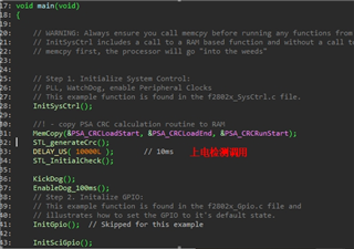
InitSysCtrl();
//! - copy PSA CRC calculation routine to RAM
MemCopy(&PSA_CRCLoadStart, &PSA_CRCLoadEnd, &PSA_CRCRunStart);
STL_generateCrc();
DELAY_US( 10000L ); // 10ms
STL_InitialCheck();
KickDog();
EnableDog_100ms();
// Step 2. Initalize GPIO:
// This example function is found in the f2802x_Gpio.c file and
// illustrates how to set the GPIO to it's default state.
InitGpio(); // Skipped for this example
InitSciGpio();
// For this case just init GPIO pins for ePWM1, ePWM2, ePWM3
// These functions are in the f2802x_EPwm.c file
//InitEPwm1Gpio(); //
InitEPwm2Gpio();
//InitEPwm3Gpio();
InitTzGpio();
// Step 3. Clear all interrupts and initialize PIE vector table:
// Disable CPU interrupts
DINT;
// Initialize the PIE control registers to their default state.
// The default state is all PIE interrupts disabled and flags
// are cleared.
// This function is found in the f2802x_PieCtrl.c file.
InitPieCtrl();
// Disable CPU interrupts and clear all CPU interrupt flags:
IER = 0x0000;
IFR = 0x0000;
// Initialize the PIE vector table with pointers to the shell Interrupt
// Service Routines (ISR).
// This will populate the entire table, even if the interrupt
// is not used in this example. This is useful for debug purposes.
// The shell ISR routines are found in f2802x_DefaultIsr.c.
// This function is found in f2802x_PieVect.c.
InitPieVectTable();
// Interrupts that are used in this example are re-mapped to
// ISR functions found within this file.
EALLOW; // This is needed to write to EALLOW protected registers
//PieVectTable.EPWM1_INT = &epwm1_isr;
//PieVectTable.EPWM3_INT = &epwm3_isr;
PieVectTable.EPWM2_INT = &epwm2_isr;
PieVectTable.TINT0 = &cpu_timer0_isr;
PieVectTable.SCIRXINTA = &sciaRxFifoIsr;
PieVectTable.EPWM2_TZINT = &epwm2_tzint_isr;
EDIS; // This is needed to disable write to EALLOW protected registers
// Step 4. Initialize all the Device Peripherals:
// This function is found in f2802x_InitPeripherals.c
// InitPeripherals(); // Not required for this example
InitCpuTimers();
ConfigCpuTimer(&CpuTimer0, 40, 10000); //��ʱ���� 10ms->10000
CpuTimer0Regs.TCR.all = 0x4001; // Use write-only instruction to set TSS bit = 0
EALLOW;
SysCtrlRegs.PCLKCR0.bit.TBCLKSYNC = 0;
EDIS;
InitEPwm2Example(SYS_PTPER);
EALLOW;
EPwm2Regs.TZSEL.bit.CBC1 = 1;
EPwm2Regs.TZCTL.bit.TZA = TZ_FORCE_LO; //EPWM3A will be forced low on a trip event.
EPwm2Regs.TZCTL.bit.TZB = TZ_FORCE_LO; //EPWM3B will be forced low on a trip event.
EPwm2Regs.TZEINT.bit.CBC = 1;
EDIS;
EALLOW;
EPwm2Regs.AQCSFRC.all = 0x05; //A B ǿ���õ�
EDIS;
EALLOW;
SysCtrlRegs.PCLKCR0.bit.TBCLKSYNC = 1;
EDIS;
KickDog();
InitAdc();
delay_xxx(100);
KickDog();
EALLOW;
AdcRegs.ADCCTL1.bit.INTPULSEPOS = 1; //ADCINT1 trips after AdcResults latch װ�����������ж�
AdcRegs.INTSEL1N2.bit.INT1E = 1; //Enabled ADCINT1
AdcRegs.INTSEL1N2.bit.INT1CONT = 0; //Disable ADCINT1 Continuous mode
AdcRegs.INTSEL1N2.bit.INT1SEL = 2; //setup EOC2 to trigger ADCINT1 to fire
AdcRegs.ADCSOC0CTL.bit.CHSEL = 15; //set SOC0 channel select to ADCINB7
AdcRegs.ADCSOC1CTL.bit.CHSEL = 14; //set SOC1 channel select to ADCINB6
AdcRegs.ADCSOC2CTL.bit.CHSEL = 12; //set SOC1 channel select to ADCINB4
AdcRegs.ADCSOC3CTL.bit.CHSEL = 11; //set SOC1 channel select to ADCINB3
AdcRegs.ADCSOC4CTL.bit.CHSEL = 9; //set SOC1 channel select to ADCINB1
AdcRegs.ADCSOC5CTL.bit.CHSEL = 2; //set SOC1 channel select to ADCINA2
AdcRegs.ADCSOC6CTL.bit.CHSEL = 1; //set SOC1 channel select to ADCINA1
AdcRegs.ADCSOC0CTL.bit.TRIGSEL = 7; //set SOC0 start trigger on EPWM2A, due to round-robin SOC0 converts first then SOC1
AdcRegs.ADCSOC1CTL.bit.TRIGSEL = 7;
AdcRegs.ADCSOC2CTL.bit.TRIGSEL = 7;
AdcRegs.ADCSOC3CTL.bit.TRIGSEL = 7;
AdcRegs.ADCSOC4CTL.bit.TRIGSEL = 7;
AdcRegs.ADCSOC5CTL.bit.TRIGSEL = 7;
AdcRegs.ADCSOC6CTL.bit.TRIGSEL = 7;
AdcRegs.ADCSOC0CTL.bit.ACQPS = 6; //set SOC0 S/H Window to 7 ADC Clock Cycles, (6 ACQPS plus 1)
AdcRegs.ADCSOC1CTL.bit.ACQPS = 6;
AdcRegs.ADCSOC2CTL.bit.ACQPS = 6;
AdcRegs.ADCSOC3CTL.bit.ACQPS = 6;
AdcRegs.ADCSOC4CTL.bit.ACQPS = 6;
AdcRegs.ADCSOC5CTL.bit.ACQPS = 6;
AdcRegs.ADCSOC6CTL.bit.ACQPS = 6;
EDIS;
// Assumes ePWM2 clock is already enabled in InitSysCtrl();
EPwm2Regs.ETSEL.bit.SOCAEN = 1; // Enable SOC on A group
EPwm2Regs.ETSEL.bit.SOCASEL = 4; // Select SOC from from CPMA on upcount
EPwm2Regs.ETPS.bit.SOCAPRD = 1; // Generate pulse on 1st event
EPwm2Regs.CMPA.half.CMPA = 0; // Set compare A value
EPwm2Regs.CMPB = EPwm2Regs.CMPA.half.CMPA >> 1;
//EPwm1Regs.TBPRD = 0xFFFF; // Set period for ePWM1
//EPwm1Regs.TBCTL.bit.CTRMODE = 0; // count up and start
// Step 5. User specific code, enable interrupts
// Initalize counters:
// EPwm1TimerIntCount = 0;
// EPwm2TimerIntCount = 0;
// EPwm3TimerIntCount = 0;
scia_fifo_init(); // Initialize the SCI FIFO
scia_loopback_init(); // Initalize SCI for digital loop back
// Enable CPU INT3 which is connected to EPWM1-3 INT:
IER |= M_INT3; //&epwm2_isr;
IER |= M_INT2; //&epwm2_TZINT;
IER |= M_INT1; //&cpu_timer0_isr;
IER |= M_INT9; //&sciaRxFifoIsr;
// Enable EPWM INTn in the PIE: Group 3 interrupt 1-3
PieCtrlRegs.PIEIER1.bit.INTx7 = 1; //TIME0
PieCtrlRegs.PIEIER9.bit.INTx1 = 1; //SCI
PieCtrlRegs.PIEIER3.bit.INTx2 = 1; // EPWM2
PieCtrlRegs.PIEIER2.bit.INTx2 = 1; //&epwm2_TZINT;
// Enable global Interrupts and higher priority real-time debug events:
EINT; // Enable Global interrupt INTM
ERTM; // Enable Global realtime interrupt DBGM
SysWork.BaseOnMode = 0;
SysWork.BaseOnFault = SYSWORK_NORMAL;
SysV_Input.V_period = 1;
SysV_Input.V_count = 0;
PI_INIT();
Leakage_INIT();
// RELAY_DC_N = 1;
// delay_xxx(10);
// RELAY_DC_P = 1;
// Step 6. IDLE loop. Just sit and loop forever (optional):
for(;;)
{
delay_xxx(10);
KickDog();
Temp_function();
//communication_PC();
if(SCI_jiange == 1)
{
SCI_jiange = 0;
#if(Debug_SCI == 1)
memset(sica_TX_buf,0,SCIA_RX_LENGTH);
sprintf(sica_TX_buf,"%04d\t",Realtemprature );//ADC_PV_dataAVE);
// sprintf(&sica_TX_buf[5],"%04d\t",ADC_PV_CURRENT_dataAVE);//ADC_HV_dataAVE);
sprintf(&sica_TX_buf[5],"%04d\t",PV_cur_init_AVE);//ADC_HV_dataAVE);
sprintf(&sica_TX_buf[10],"%04d\t",PV_Current_SYSMAX);
sprintf(&sica_TX_buf[15],"%04d\t",(int16)ADC_PV_CURRENT_data);
// sprintf(&sica_TX_buf[15],"%04d\t",(int16)ADC_PV_dataAVE_mppt);
sprintf(&sica_TX_buf[20],"%04d\t",PI_Ipv.Ref);
// sprintf(&sica_TX_buf[20],"%04d\t",ADC_PV_data);
sprintf(&sica_TX_buf[25],"%04d\t",PV_MpptPara.Vref);
sprintf(&sica_TX_buf[30],"%04d\t",pv_pp);
sprintf(&sica_TX_buf[35],"%04d\t\r\n",pv_ii);
// sprintf(&sica_TX_buf[30],"%04d\t",pv_pp);
// sprintf(&sica_TX_buf[35],"%04d\t\r\n",pv_ii);
SciASendFrame(sica_TX_buf,40+2);
//Get_DebugCmd();
#else
;
#endif
}
if(Get_SCIRX_FG == 1) //�յ�һ֡����
{
Get_SCIRX_FG = 0;
#if(Debug_SCI == 1)
Get_DebugCmd();
#else
;
#endif
memset(sica_RX_buf,0,SCIA_RX_LENGTH);
scia_RX_count=0;
}
if (Flg_100ms)
{
Flg_100ms = 0;
/////////////////////STL/////////////////////
// STL_RunCheck();
ProtectProcess();
LED_Control();
}
}
}
void delay_xxx(unsigned int xxx)
{
unsigned int sub_ii;
for(sub_ii=0;sub_ii<xxx;sub_ii++)
{
;
}
}
My customer use F28021 which need ETL certification.
I tell customer use the link file to do this.
https://www.ti.com/tool/IEC60730SWPACKAGES#downloads
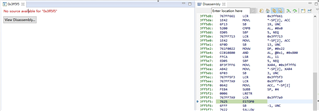
After they use the file,compile passed,but when download ,it can't run normally.
During the simulation, the program stopped at 0x3ff5f5 and could not run anymore.