This thread has been locked.

If you have a related question, please click the "Ask a related question" button in the top right corner. The newly created question will be automatically linked to this question.

Doubts about regenerative braking project with F28335

Other Parts Discussed in Thread: CONTROLSUITE

Hi,

i'm new in this forum. First of all, i hope i can help you and you can help me and sorry for my english.

I am an electrical engineering student and want to do my final project on regenerative braking. We want to make a system like this:

Battery + DC / DC boost + 3 phase inverter + permanet magnet motor.

In the system there is another DC / DC ready connected to the battery which uses the energy recovered during braking for other tasks such as air conditioning.

We purchased the Renewable Energy Developer's Kit, the Explorer Kit and Peripheral Dual Motor Control and PFC kit. We also want to program the processor F28335 using MATLAB support for this processor. We know that support for MATLAB is for the Starter Kit, but we want to program the processor using the other kits. Is it possible?

And what you recommend us to develop the project?

Thanks in advance,

Carlos Camacho (University of Barcelona, Spain)

  • If possible please post the block diagram of your system .. I was not able understand the configuration .... I am assuming the recovered energy will come from your drive.. if that is the case the second DC/DC coverter will hang from your DC bus to charge the battery ...

  • Hello,

    you can see the block diagram in the attached file. In that patent, The recovered energy can power the air conditioning motor, but we only want to measure how much energy is recovered during braking using a DC / DC converter connected to a load such as a resistance, which dissipates the energy recovered.

    In the project we are studying the regenerative braking using simulations with MATLAB and PLACS, but we also want to make a real device to verify and study this fact.

    thanks

    Carlos

    EP1306262A2.pdf
  • Carlos,


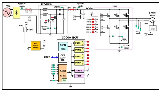
    You can try using the HVMTRPFC Kit for this purpose,  the kit has a boost and an inverter stage on the board, below is the snapshot of the stages on the board,


    The stages on the board are connected together through banana cables, so all you would need is to connect a battery to the PFC Boost stage,

    A software for Boost and motor inverter is available, through controlSUITE with PFC boost on CLA, 

    From some practical experiences, the kit has nothing about regenerative braking on it, so if you break the motor you can see the Vdc Bus rise as the spare energy is regenerated. You would need another stage at the BS4-5 (an external board), which should be able to tap into this energy,

    The challenge would be communicating between the the stages on this board and the external stage you would need to connect to this, there is CAN and SCI options available,

    if you design your own board all three stages can be controlled using one single controller,

    Also this board is not designed with most optimal power electronics which you would need to spend time on   ,

    -Manish Bhardwaj

  • Thanks for the information.

    However, as I said before, we have purchased three kits: peripheral explorer kit, Renewable energy developer's kit and Dual Motor Control and PFC Dev Kit

    We want to create the system I've explained before with these kits if possible. What is the best for our purpose?

    On the other hand, where I can find the characteristics of the engine included in the Dual Motor Control Kit? Power, torque, ...

    Thanks,

    Carlos Camacho

  • Mohammed:

    you are the author of the schematic diagram of the "Renewable Energy" kit?

    I ask because I need to know what software was used to create these schematics and boards.

    I tried to open files with Eagle, gEDA and PROTEL and can not open the files.

    Greetings Carlos 

  • Hello Carlos

    I am no longer with Texas Instruments and don't know the current development status .... I am sure TI folks will answer your question.  I believe these are developed using Express PCB (http://www.expresspcb.com/)  .. it is a free download but unfortunately not compatible with any other design software (at least I am not aware of any).

    Regards

  • Thanks for the information.

    Regards Carlos

  • Welcome .. am curious to know more about your system ... if possible share more information on your development ... is this a new product targetting any certain power range or application?

  • My project is to use the TI Renewable Energy Kit  as a basis for the realization of a master's thesis on Renewable Energy. The idea is to study the feasibility of implementing a  "modular micro  inverter", I understand that the current trend is to develop highly reliable equipment that will last many years.
    Frecuently in developing countries such as Argentina the electrical / electronic equipment is repared , this is the motivation to the mentioned study. I understand that a modular equipment as a desktop "PC" would be more easily repaired.
    This point has an effect on the environmental impact throughout the lifecycle and the cost of the Micro Inverter. I hope the idea are understood :-)
    Regads Carlos

  • Thanks for your answer... yes, it makes sense and in fact it is a complicated problem... You will be challenged by multiple contradicting requirements like reliability, performance, ease of servicing and low cost.....

  • Arefeen: how are you?
    I was reviewing the DSP program renewable energy kit and I can not understand where does the PWM modulation.
    Do you know what type of modulation controller makes the DC-AC stage?
    In section 2.2 of the document "Implementing a Digitally Controlled Renewable Energy System with C2000 Micro-Controllers"says that both the frequency and amplitude are adjusted depending on error.

    Many greetings
    Carlos