This thread has been locked.

If you have a related question, please click the "Ask a related question" button in the top right corner. The newly created question will be automatically linked to this question.

TMS320F28035: PWM external sync leads to continuous HIGH level

Part Number: TMS320F28035

Hi,

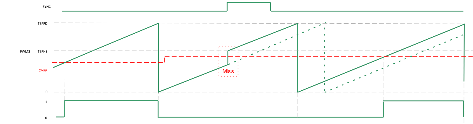
While prototyping a new device with external sync, we observed that, if the CMPA value is never reached due to TBPHS reload at sync, the PWM is maintained at HIGH level. We are using the 6 PWMA peripherals, each one being phase shifted by PI/3 from the precedent:

  1. 60°
  2. 120°
  3. 180°
  4. 240°
  5. 300°

Here is a picture explaining the problem (the last one is our concerning case):

Here is our PWM configuration code:

void pwm_RegisterConfiguration(int16 n, Uint16 period, int16 mode, uint16_t phase)
{
    // Time Base SubModule Registers

    (*ePWM[n]).TBCTR = 0;
    (*ePWM[n]).TBCTL.bit.CTRMODE = TB_COUNT_UP;
    (*ePWM[n]).TBCTL.bit.HSPCLKDIV = TB_DIV1;
    (*ePWM[n]).TBCTL.bit.CLKDIV = TB_DIV1;

    (*ePWM[n]).DBCTL.bit.OUT_MODE = DB_DISABLE;     // disable dead-band module

    // Master config
    if (mode == PWM_MASTER)
    {
        pwm_MasterSlaveConfig[n-1] = PWM_MASTER;

        (*ePWM[n]).TBCTL.bit.PHSEN = TB_DISABLE;
        (*ePWM[n]).TBCTL.bit.SYNCOSEL = TB_CTR_ZERO; // sync "down-stream"

        (*ePWM[n]).TBCTL.bit.PRDLD = TB_SHADOW; // set shadow load
        (*ePWM[n]).TBPHS.half.TBPHS = 0;
    }
    // Slave config
    else if (mode == PWM_SLAVE)
    {
        pwm_MasterSlaveConfig[n-1] = PWM_SLAVE;

        (*ePWM[n]).TBCTL.bit.PHSEN = TB_ENABLE;

        if (n == PWM1)
        {
            (*ePWM[n]).TBCTL.bit.SYNCOSEL = TB_SYNC_IN; // sync "down-stream"
            (*ePWM[n]).TBCTL.bit.PRDLD = TB_SHADOW; // set shadow load
            (*ePWM[n]).TBPHS.half.TBPHS = 0;        // this value should stay at 0 in any case for PWM1
        }
        else
        {
            (*ePWM[n]).TBCTL.bit.SYNCOSEL = TB_SYNC_IN; // sync flow-through
            (*ePWM[n]).TBCTL.bit.PRDLD = TB_SHADOW; // set Immediate load
            (*ePWM[n]).TBPHS.half.TBPHS = (period - phase);
        }
    }

    // Mandatory to fill TBPRD after setting an IMMEDIATE register
    // note : it's not mandatory for SHADOW register
    (*ePWM[n]).TBPRD = period - 1;                  // PWM frequency = 1 / period

    // Counter Compare Submodule Registers
    (*ePWM[n]).CMPA.half.CMPA = 0;      // set duty 0% initially
    (*ePWM[n]).CMPB = 0;                // set duty 0% initially
    (*ePWM[n]).CMPCTL.bit.SHDWAMODE = CC_SHADOW;
    (*ePWM[n]).CMPCTL.bit.LOADAMODE = CC_CTR_ZERO;
    (*ePWM[n]).CMPCTL.bit.SHDWBMODE = CC_SHADOW;
    (*ePWM[n]).CMPCTL.bit.LOADBMODE = CC_CTR_ZERO;

    // When CPU forces a PWM it is forced without sync
    (*ePWM[n]).AQSFRC.bit.RLDCSF = PWM_AQSFRC_LOAD_IMMEDIATELY;

    // Action Qualifier SubModule Registers: DISABLE ALL
    (*ePWM[n]).AQCTLA.bit.ZRO = AQ_NO_ACTION;
    (*ePWM[n]).AQCTLA.bit.CAU = AQ_NO_ACTION;
    (*ePWM[n]).AQCTLA.bit.CBU = AQ_NO_ACTION;
    (*ePWM[n]).AQCTLA.bit.PRD = AQ_NO_ACTION;

    (*ePWM[n]).AQCTLB.bit.ZRO = AQ_NO_ACTION;
    (*ePWM[n]).AQCTLB.bit.CAU = AQ_NO_ACTION;
    (*ePWM[n]).AQCTLB.bit.CBU = AQ_NO_ACTION;
    (*ePWM[n]).AQCTLB.bit.PRD = AQ_NO_ACTION;
}

When starting the function, we set the AQCTLx register as follow:

void PWM_EnablePwmADisablePwmB()
{
    PWM_list_e i;

    for (i = PWM1; i < PWM_NUM_PWM_IN_USE+1; ++i)
    {
        // Action Qualifier SubModule Registers
        ePWM[i]->AQCTLA.bit.ZRO = AQ_CLEAR;
        ePWM[i]->AQCTLA.bit.CAU = AQ_SET;
        ePWM[i]->AQCTLA.bit.CBU = AQ_NO_ACTION;
        ePWM[i]->AQCTLA.bit.PRD = AQ_NO_ACTION;

        ePWM[i]->AQCTLB.bit.ZRO = AQ_CLEAR;
        ePWM[i]->AQCTLB.bit.CAU = AQ_CLEAR;
        ePWM[i]->AQCTLB.bit.CBU = AQ_CLEAR;
        ePWM[i]->AQCTLB.bit.PRD = AQ_CLEAR;

        ePWM[i]->AQCSFRC.bit.CSFB = PWM_FORCE_CONTINUOUS_LOW;
    }
}

Is there a special configuration needed to ensure the good behavior of the PWMs in this very particular case?

Best regards,

Alexis L.
Embedded Software Engineer

  • Alexis,

    This is the intended operation of the PWM module. The CMPx comparison with the TBCTR is an "equal to" comparison not a "equal to or greater than" comparison. 

    There are a few things that can be done to avoid this issue.

    1. Synchronized PWMs should always be synchronized by the slowest PWM period. This avoids continuous, forward jumping, discontinuities as you have shown in your diagram.
    2. Avoid syncing near your compare events.
    3. Detect in SW and use the SW force sync if you are synchronizing near your CMPx value.

    Are you using external sync to synchronize two c2000 devices? 

    Why is your TBCTR value jumping every period? Are you synchronizing at a period shorter than your configured PWM period?

    Do you need continuous synchronization? Many applications can synchronize once and then be OK, this depends on clock drift and other factors.

    Regards,
    Cody 

  • Cody,

    First of all, thank you for the fast reply.

    1. Our 6 PWMs are at the same frequency, 50KHz. What is the required precision of the sync signal's frequency ? 
    2. Given that our PWMs are dephased, we can't predict if we are synchronizing near of it. It depends on phase and duty cycle.
    3. Sync is managed directly in the PWM module, SW only interfere during configuration steps, otherwise only CLA manages PWM's duty cycle.

    We are aiming to use it to sync two C2000 devices, yes.

    The TBCTR is jumping because the refresh is reloading the TBPHS value. In a case of desync, it will cause a jump in TBCTR as seen in the diagram.

    We need continuous sync due to system requirements. We estimated a maximum drift of 4Hz between two devices.

    Regards,
    Alexis

  • Alexis,

    there are a lot of intricacies going on here, and obviously I don't know your system very well. I'm going to do my best to provide some guidance.

    Our 6 PWMs are at the same frequency, 50KHz. What is the required precision of the sync signal's frequency ?

    I'm not sure what you mean. The important thing is that if you have a low-frequency PWM and a high frequency sync signal then the sync signal will cause the lower frequency PWM period to increase by causing discontinuities in the TBCTR. If two PWMs need to be synchronized then the slower PWM must provide the sync signal to the faster PWM.  

    Given that our PWMs are dephased, we can't predict if we are synchronizing near of it. It depends on phase and duty cycle.

    If your PWMs are "dephased" why are you synchronizing them? If they don't have a phase relationship then I don't know why you would try to synchronize them. If this is actually the case I can just accept it and move on.

    If you have no idea what frequency or when sync's could occur then this issue could happen. Perhaps one way to work around this is to implement a CLA task which is triggered by a sync event which checks if CMPx<= TBCTR && TBPHS and takes an action on that. 

    Regards,
    Cody

  • Cody,

    I'm not sure what you mean. The important thing is that if you have a low-frequency PWM and a high frequency sync signal then the sync signal will cause the lower frequency PWM period to increase by causing discontinuities in the TBCTR. If two PWMs need to be synchronized then the slower PWM must provide the sync signal to the faster PWM.  

    This will be clearer with the following picture:

    We have two devices, each one have a C2000 chip which controls 6 dephased PWMs. Each one shall produce a 50kHz PWM, -/+ 4Hz.

    Here is our regular configuration:

    • 0 <= CTR < CMPA  --> High Level
    • CTR >= CMPA        --> Low Level
    • Problem : resync with high speed signal was causing the previously described problem

    I inversed the ouput:

    • 0 <= CTR < CMPA  --> Low Level
    • CTR >= CMPA        --> High Level

    With this change, if one device resynchronization forced one of the PWM's CTR to be reloaded higher than CMPA, the ouput is maintained to low level.

    In order to avoid permanent level maintenance, we are thinking to reduce the SYNC signal frequency for example to 1kHz. Can you confirm that the level maintenance can only occurs during the "resync period", as shown below ?


    Regards,
    Alexis

  • Alexis,

    Correct, In this case the low level will only occur for one period after the sync event. If you slow your sync pulse down to 1Hz then the devices should remain tightly in sync because the oscillator drift will not be that large. And  with this strategy you will experience this low pulse at most once per second.

    Regards,
    Cody