This thread has been locked.

If you have a related question, please click the "Ask a related question" button in the top right corner. The newly created question will be automatically linked to this question.

TMS320F28069M: need guideline to program tmsf28069m using xds100v2

Part Number: TMS320F28069M
Other Parts Discussed in Thread: MOTORWARE,

Hi team,

after debugging and running the modified motorware lab12b code on the F28069M I needed it to work without connecting it to the XDS100 stick. But it seems that after disconnecting it from the XDS100 and rebooting the F28069M doesn't run. I suppose we have to "burn" the code or something? i have tried both "flash" and "release" configurations in project properties. How do I get to work just by supplying power to the board, without the board being connected to the XDS100?

Thank you very much for your help.

Best regards,

  • Zhonghui,

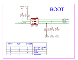
    Can you confirm that on the LaunchPad the Boot pins are configured for "Get Mode" as shown below?  You will need to have the flash configuration loaded as you mention.

    Best,
    Matthew

  • Hi Matthew,

    Thanks for quick reply, Its a custom made board and attached is the XDS interface schematic.The emulator can be removed. I see some of the pins are not pulled low. will try pulling them low and then update. if any other change is recommended please let me know.

    Another point, Do we need to pull down GPIO34 . As I am using 28069M ic.

    Please provide ref of relevant document.

    Thanks a lot.

    Best regards,

  • Zhonghui,

    The JTAG termination is on page 32 of the device datasheet: https://www.ti.com/lit/ds/symlink/tms320f28069.pdf

    You can find the boot pin definition on page 46 of the same document.

    Best,

    Matthew

  • Hi Matthew,

    Here below is the latest feedback from the cusomer. Please help to continue to suport the customer.

    ------------------------------------

    Made the required changes in the HW, will be testing final solution today and update.

    Updated the HW as
    1. GPIO34 PullUP 10K
    2. GPIO37 PullUp 1K
    3. TRST Pulled down 2.2K
    We are using SCIA as control port (converted to RS485 using THVD1510D ic) and using following pins
    GPIO6 as Data Direction control, Output mode
    GPIO29 as TX, GPIO_29_Mode_SCITXDA
    GPIO7 as RX, GPIO_7_Mode_SCIRXDA
    not using scia interrupt.
    Some other pins are used as various GPIOs.
    Configured and compiled the program using Flash option and "Flashed" the program in the circuit tms320f28069m.
    Observation1- When circuit was booted with debugger (xds100v2) connected, it worked perfectly as per program.
    Observation2- While being tested as above if debugger was removed without rebooting or circuit rebooted without connected debugger, all functions worked fine as indicated by status LED and Motor operation in manual mode but commands given through RS485 didn't work at all. It looks like scia is just not receiving any signal at all as status led doesn't show it.
    Please Guide

    The question is why it needs connected debugger. I have verified that flash is loaded with updated machine code by changing behaviour of status led.

    ------------------------------------

    B.R.

    Eric Ba

  • Eric,

    If they have added some LED indicators that show the code is executing in standalone I would expect things to work as expected(working standalone is usually where there are issues).

    I would suggest that with the debug probe/CCS connected they issue a "Reset" and then Run to Main, and then run to see if the SCI works.  This should simulate the standalone boot mode, and if we see there are issues we can debug using CCS. 

    Based on what you've said I suspect either some uninitialized variables or maybe a missing EALLOW instruction that blocks a write to a register.

    Best,
    Matthew